G7 Power Supply Help

GroupDIY Audio Forum

Help Support GroupDIY Audio Forum:

This site may earn a commission from merchant affiliate links, including eBay, Amazon, and others.

clister01

Well-known member
Joined
Aug 17, 2005
Messages
80
Location
Los Angeles
Hey Guys,

If someone has a little bit of time I need some help with the G7 power supply. I've been scouring through the METAs and for the life of me I can't figure out how to wire up the toroids/psu. I'm using the Avel Lindberg toroids from Greg's part list.

http://www.avellindberg.com/transformers/y23_range_specs.htm

model numbers Y236001 and Y236003

Here's more data on the transformers as far as the leads go:

t1.jpg


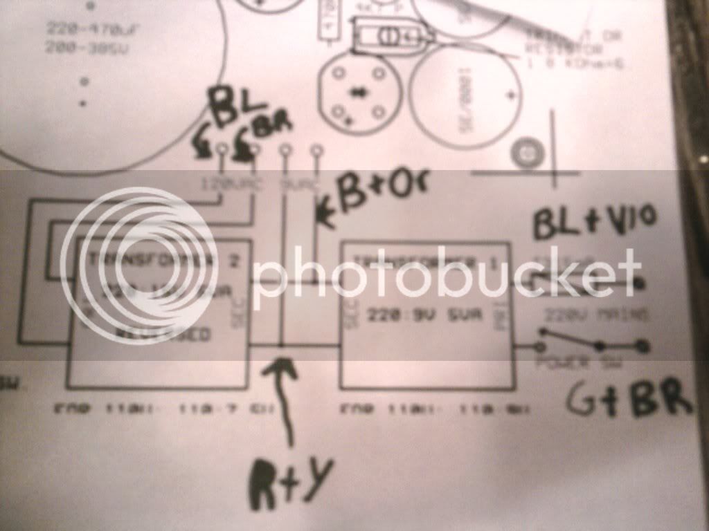
and here's what I'm looking at with my eyes:

PSU1.jpg


I'm just a little lost. Can someone give me a detailed "red wire to green wire" type description of all hookup points for the toroids from the inlet to the PCB? And if you've got the time after that I'd really appreciate a little bit of explanation on this one. A "why things get hooked up the way they do" sort of thing.

Any help is appreciated. Thanks so much,

Cameron
 
Hi!

If you have 110V mains it should be something like this....

G7trannies.gif


The colour codes are based on the drawings you posted.

Primaries in parallel; two 9V secondaries in parallel connected to two 15V secondaries in parallel on the second, reversed transformer. Tap off your heater supply from across these.

Connect the two 110V coils of the reversed 15:220 in series to give the HT

Hope that helps a little!
 
That helps so much. But just to be clear then. I connect the BLU and BRN wires on the reversed 220 to the PCB and leave the GRY/VO unconnected?

-Cameron
 
just to help me understand: why wouldn't we want to leave the secondaries of the first transformer independent - 1 to the heater supply and 1 to the second transformer? thanks, Ben
 
> why wouldn't we want to leave the secondaries of the first transformer independent - 1 to the heater supply and 1 to the second transformer?

I dunno. But generally:

A) either way works; everything is isolated as needed

B) often the two loads are not the same wattage. If split, you either overload one winding or buy double-size at higher cost. If paralleled, the full transformer rating is available.
 
I am glad I found this thread. I took a picture to help me and some kind soul to figure this out without blowing it or me up.
Here is a pic;
G7transwiring1.jpg


I have the same transformers and that chart of how to hook up wires helped a lot. I am a little confused on where they hook up on pcb and such. Am I close? BL= blue, BR=brown, B=black, G=gray.

Coming from the wall the Gray and brown hook to positive right? I can tell that the incoming power from 220 in pic is positive and the other one with fuse is negative. Also is one supposed to be able to tell how these are connected from the schematic? I am just getting familiar with them but I don't see how it tells you about connecting these very clearly like the above chart did. TIA, Mark.
 
marktokach said:
I don't see how it tells you about connecting these very clearly like the above chart did.

Well the schematic works for different brands of transformers, which may have different coloured wires. So you really need the schematic and the data sheet to work it out.

can tell that the incoming power from 220 in pic is positive and the other one with fuse is negative

Well strictly it's alternating current (AC), so 'live' and 'neutral' are the preferred terms. In this case the mains transformer primary doesn't know or care which is which. So if you connect them backwards it'll still work.

Anyway, your sketch does look like it matches the diagram above. (I haven't used that brand of transformers - check that the original post's colour codes are correct!)

z50


Latest posts

Back
Top