HI-Z input for Amek-2500 based preamp

GroupDIY Audio Forum

Help Support GroupDIY Audio Forum:

This site may earn a commission from merchant affiliate links, including eBay, Amazon, and others.

modulay

Well-known member
Joined
Aug 6, 2008
Messages
63
Location
Spain
Hi everyboody.

I'm building an Amek 2500 preamp based on this schematic:

http://www.dmlab.jexiste.fr/Amek M2500/amek2500micpre_schematic.pdf

I'd like add to it an instrument input, so I thought to use this opamp based DI stage,using relay for switching between mic input XLR connector and DI stage output:

http://www.jlmaudio.com/JLM DI Schematic.pdf

But I have some questions about it...

¿Why two opamps? ¿Wouldn't it work fine with just one of them?

I'd like to use OPA604 instead of OPA2604, and supply it with a symmetrical rail, so I could supress signal offset circuitry.
¿What do you think about that?

Thanks.
Jose
 
[quote author="modulay"]¿Why two opamps? ¿Wouldn't it work fine with just one of them?[/quote]
Depending in the input-Z of the mic-pre that DI is put in front of it may require more muscle to keep things healthy. So two working together.
If it's known there won't be (say a) 300 Ohms input connected (as can be for a Neve-micpre with 2 || input windings) then it might be OK with just one opamp; I don't recall those OPA-loading-spec from memory)
 
I assume that you are talking about load ¿aren't you?
By default, that preamp uses 1kohm for Ri resistor, wich establishes input impedance, but I'd like this impedance be adjustable by trimpot...so that muscle will be necessary in anyway.

This is related technical data for OPA604

 
Yep, talking about load, so the muscle would be good to have.

I'd make a few switchable input-Z settings using fixed resistors, not a trimpot, but I can't guarantee you'll be having problems using the trimpot :wink:

I don't think though that there's much sense in using this DI in front & then controlling its load by means of the trimmer or something.
If you want to make a DI/buffer sweat for some colour, the Great River DI-circuit (also around here) might be a better one then.

Bye,

Peter
 
Well, in my case, variable pre input impedance is a purpose for mic input uses, not a sound color playing for Hi-Z.

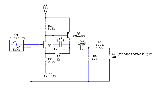
I've found this schematic for Great River.It looks fine.

DI_input.gif


I suppose the sense of using fixed resistors for input impedance adjust resides in a better control and knowledge by the user ¿is that okay?
 
[quote author="modulay"]Well, in my case, variable pre input impedance is a purpose for mic input uses, not a sound color playing for Hi-Z.[/quote]
That's it ! And be sure to re-adjust for highest mic-pre input-Z when the DI is used. (If you put the DI-circuit you could get fancy and make that 'automatic')

I've found this schematic for Great River.It looks fine.
That's the topology. Dunno about values, I see this one runs on +/-24V while the original on just +24V.

I suppose the sense of using fixed resistors for input impedance adjust resides in a better control and knowledge by the user ¿is that okay?
I don't know much about the potential noisyness of trimmers (the material itself, wiper-noise etc), hence the preference for (popless) switching of fixed resistors. But I don't say it can't be done.

Bye,

Peter
 
I'm going to build JLM DI stage,but with some changes:

- Symmetrycal supply.
- No offset circuitry.
- OPA604 instead of OPA2604.


I've held R2 at non-inverting input.
Would be this correct?
Is 2.2Meg an appropiate value for R2 ?
 
R2 is fine (anything between 1M and 10M works fine) but R7 and R8 should have a lower value, take 100k. Electrolytics have relatively large leakage currents and these resistors need to swamp those.

But in any case you could skip C5/C6/R7/R8 and just connect directly to the preamp as it is AC coupled already. The switch might click a bit that way but who cares for that application.

Samuel
 
Yep, preamp input is already coupled. I thought as well about that...

But, if skiping C5,C6,R7 and R8...what about reflected output impedance?
How to connect "-" output? wiring to signal ground?
 
Connecting the minus input to ground via a pair of paralleled 51 Ohm resistors gives a theoretical advantage with respect to interference rejection but in practice just grounding it will very likely work fine.

Samuel
 
Can I use 47 or 56 (maybe 100?) ohm resistor instead 51?
And...can I use a 5532 instead OPA...?
Thanks!
 
Maybe the OP275 could work well...I think it has a Jfet input....and it is a little better then the 072.

This is my HiZ schematic, and it works well...I don't know if I made any errors, but...it works.
I'd like to build your HIZ because it seems to be more simple, with less components...
Hi%20Z%202.GIF
 

Latest posts

Back
Top