SSL 4000 channel compressor

GroupDIY Audio Forum

Help Support GroupDIY Audio Forum:

This site may earn a commission from merchant affiliate links, including eBay, Amazon, and others.

Manifold

Member
Joined
Mar 11, 2005
Messages
21
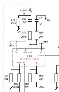
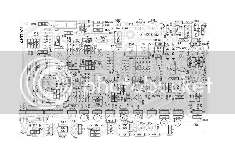
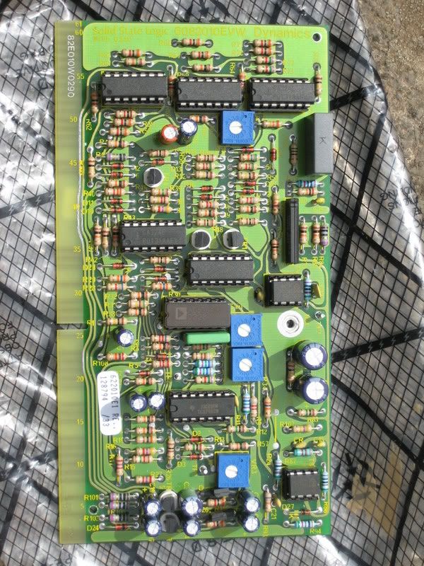
Does anyone else have the SSL 82E10 schematic that I might be able to get a hold of. I've been studying this one and I could be wrong, but I think there is a portion of it that is not complete. Down in the left hand corner of the bottom of the first page, if you look at the input to the VCA, pin 2 after R78 and pin 7 appear to have had the lines erased showing where they were connected.

If anyone has one or if anyone could just tell me how these pins should be connected, I would appreciate it.

I've looked around the net for another copy of the schematic, but that is the only one I can find.

same url as above:
http://www.ka-electronics.com/images/SSL/ssl_82E10.pdf
 
Hi, looks totally right to me, audio input via C10, R78, R79. Pin 7 +v

Are you re-engineering or hooking up a dynamics card?

DynamicsIn.jpg
 
Thanks for the reply. That picture that you posted makes much more sense.

R78 in the link that I posted is connected to pin 2, which doesn't make a lot of sense, at least to me.

I figured pin 7 on the link I posted was supposed to go to +15, but since the V- (pin 5) had a resistor before it, I wasn't sure if pin 7 should as well.

Although, looking at the picture you posted, I noticed that there is a CV marking going into pins 2 & 6. Is that just meant to signify that the ground reference for the Control voltage and the ground reference for the audio are to be kept separate?

I'm doing all of this for re-engineering. I was wanting to see if I could make one of these for fun. I've always liked the way the channel compressor sounds on certain things.

Thanks again for the reply.
 
Have you tried a 2181 in place of the 2151? You are showing it as a direct replacement with no mods, I have not yet tried this but I have a bunch of 82E10 cards to repair......
 
Mine is drawn, with help from a very kind German friend.. from a G series card. I purchased this as a new spare directly from SSL in 2004 (test date sticker 2003) for future re-engineering b4 they dumped all the 4k stuff. It was fitted with the 2181A as standard.. I seem to remember no changes, but would have to check the BOM.

4Kdre-eng.jpg


IMG_2970.jpg


IMG_2971.jpg
 
You wouldn't, by chance, be willing to send me a copy of the schematic you have would you? If not, I understand, but if you could I would definitely appreciate it.
 
I`m designing a pcb for this compressor, I will try to replace the SD536 with a that2252.

Sintech, did you had some problem with your clone? some people have reported some problems when cloning this compressor.

Of course I must ask because it would save me some time, it would be possible that you made public your layout? if not, thanks for the pictures.
 
some people have reported some problems when cloning this compressor.

Only problem I've run into is that 1V5 Zener diodes seems to be polarity-marked randomly by any manufacturer - so you need to measure for yourself before mounting. Schematic even warns about this..

Jakob E.
 
WOW!!

This would be an awesome DIY project . Are any of you guys planning on doing a pcb run , or publishing a layout for us home etchers?!!

I'd love to give it a go....these things are amazing little workhorses.

Well done to anyone out there working on this!

cheers ,

nEon.
 

Latest posts

Back
Top