Ya, I don't really understand what you mean. My LED's extend out a few inches and are shrinkwrapped, but they don't sit tight in the front panel holes, so they slip out. I tried hot glue, but by the time the front panel was nearly on, a few had broken loose. Man, is this case a bitch. Everything is so tight and bulging and squished, it's so difficult to get anything to work. The PSU should definitely NOT have been inside this unit, and I wish I had thought of this before.
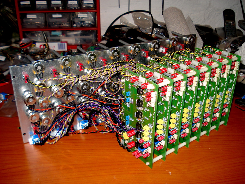
Gonna keep trying some things. On a good note, all 8 of my channels are wired, tested and calibrated, and sound fantastic!
Thanks,
Sig
EDIT - it appears there are certain LED's that fit very tight and snug, and some that don't, even though they're all 3mm. I happened to pull one out of the drawer for the power, and it fit perfect. So, I guess I have to cut all these off and try to find some replacements that fit better. :'(


 (sorry it's a translation of what we got here for paste type)