Need help with a simple circuit design - touch switch

GroupDIY Audio Forum

Help Support GroupDIY Audio Forum:

This site may earn a commission from merchant affiliate links, including eBay, Amazon, and others.

Emperor-TK

Well-known member
Joined
Jul 14, 2004
Messages
1,076
Location
NJ, USA
I'm building a capacitive touch switch according to this article:

http://www.edn.com/article/CA498777.html

touchswitch.jpg


The circuit is easy to tune when I'm using a bare lead for the touch plate, but I need to use an insulated touch plate for this application. At the input to IC1B, I get 8.6VDC untouched and 0.4VDC touched, which is well suited to switch states on the Schmitt trigger. However, with a dielectric over my touch switch, I get 8.6VDC untouched and 7.0VDC touched, which won't change states on the Schmitt trigger.

My questions are:

1. Is there anything I can do to get the low voltage (touched) state to be lower without changing the capacitance of my touch switch?

2. I need to trigger some audio samples which are currently triggered by a mechanical switch. My initial thought was to hook up 12v relays to the outputs of IC1B and IC1C. Is there a better way to do this with transistors? The outputs from IC1B and IC1C are 0V in the off state and 12 in the on state.

Thanks,
Chris
 
You can experiment with the value of R5 but you may end up pressing your finger much harder to change state.

It's been a long time but at some point I designed touch sensors based on Quantum Research's capacitive sensor ICs QT320 and QT113. These may be obsolete by now but I am sure they will have a better version. They are very easy to use and very reliable.

By the way, thank you for bringing up this topic which made me check the sample parts I had on the shelf and discovered that the batteries in the box were about to explode.
 
One thing to try with the design as it is now is a larger touch plate. Caps added in series(touch pad and dielectric and then the human) are smaller than the smallest value.

Q1 being a fet I wonder if the Vgs off matters in this circuit. Maybe try another fet.

Or to help it out make the plate two pieces ground one side and connect the other to the input then place a dielectric over the touch pad pair

maybe circle(touch pad input) in a ring(ground)
 
I don't have time at the moment to think about optimizing this too much---maybe in a bit. However, like so many of these sort of free circuits there is a fundamental flaw, one shared with a patent* I somewhat reluctantly wound up with my name on when I helped the primary inventor come up with a short-term fix.

That is: the circuit relies on pulling energy away from the touch pad node to change states. However, in a high noise environment note that you can also inject noise that you are picking up, and this noise can interefere with the change in state.

An approach that I developed at the time of crisis for Mr. Horton involved a synchronous rectification technique. It's incredibly more noise-immune. It's also at this point unprotected and proprietary.


*US 7106221
 
I checked QT site and 113 is still available. There is the link.

http://www.qprox.com/products/Page-16035/Page-16390.html

Ignore the statement says that 110 families are not recommended for new designs. That is just a jargon for automated/volume manufacture.

They also have evaluation kits that are very reasonably priced (I have about four different ones here that were left from 2002) and these alone will save you a lot of time and effort if you only need one off.
 
Find something that works real good and then take it apart or find the schematic.


I blew up the cap switches in one of the elevators at the Disneyland Hotel back in 63.
Those switches were so cool that I kept going up and down, pushed every button at once, having a good ol time.
Then the panel went black and I high tailed it back to the room.
Came back a few hours later and the butt cleavage repairman guy was cussing at the panel.
I was only 8 years old, so that was my first terrorist attack on the Disneyland Hotel.
 
[quote author="Emperor-TK"]I'm building a capacitive touch switch according to this article:

http://www.edn.com/article/CA498777.html

touchswitch.jpg


The circuit is easy to tune when I'm using a bare lead for the touch plate, but I need to use an insulated touch plate for this application. At the input to IC1B, I get 8.6VDC untouched and 0.4VDC touched, which is well suited to switch states on the Schmitt trigger. However, with a dielectric over my touch switch, I get 8.6VDC untouched and 7.0VDC touched, which won't change states on the Schmitt trigger.

My questions are:

1. Is there anything I can do to get the low voltage (touched) state to be lower without changing the capacitance of my touch switch?

2. I need to trigger some audio samples which are currently triggered by a mechanical switch. My initial thought was to hook up 12v relays to the outputs of IC1B and IC1C. Is there a better way to do this with transistors? The outputs from IC1B and IC1C are 0V in the off state and 12 in the on state.

Thanks,
Chris[/quote]

Although my cautions apply as before, the first line of attack would be to see how much larger you can make R3. Probably the optimal configuration would be drive level maximum and R3 increased to just reliably have a high state at the first 40106 input---which should be determined by pin 4 being low, not by probing pin 3 as it is so easily loaded down.

By the way, unless the pot wiper is open-circuited, R5 is superfluous.

You are fighting the input and Miller capacitances of the JFET. A more complex circuit in that vicinity could reduce these---but the ambient noise sensitivity goes up up up.
 
Have you tried running an opamp in open loop?

Or is that what those IC blocks are, comparators?

You could base the switching on the human being a walking antenna, instead of a walking capacitor.
 
> Is there a better way to do this

EDN essays are rarely as wonderful as they seem.

As bcarso sez, this one may be a less-favorable basic plan.

Are you working indoors? Put your pad on a CMOS gate input, with 100K series and 10Meg||100p to ground. Un-touched, the gate output may stay at zero. Touched, the 60Hz field in the room caught by a large surface (user's body) may wobble the CMOS gate into rail-rail bounces. You have to fiddle shunt capacitance, pad area and stray capacitance to room and to CMOS ground.

I found such a scheme utterly reliable in fluorescent-lit schoolrooms, and just as good around the house.

On the face of it, it can't work a mile into undisturbed woods, unless you can adjust sensitivity for wilderness or civilization. (Idea For Discard: use a dummy plate to sample ambient crap and adjust sensitivity on finger-pad.)

Don't ask what cap-value.... this was a long time back and today I don't even remember what drugs were in fashion then, much less some hasty-hack's caps.

The other way to go is a 2-part pad, often disk and ring. One part has a high-amplitude high frequency wave, the other is sensor. When a finger bridges ring and disk, coupling increases, you sense the larger crap. I believe this IS the system which CJ was researching. In dry air with good wool carpet, you shuffle and then hold your finger 1/8" from the disk and throw a 30KV static-shock into the sensor circuit. When they finally got the gate-protection PRR/CJ-proof, this would call the car without actually touching the disk. Before that, it might call or it might blow its brain out.
 
They are schmitt-trigger inverters CJ. Go up to about 2/3 of Vsupply and the output goes negative. Then you have to go down to 1/3 of Vsupply to make the output transition to positive. Those thresholds are not guaranteed, but typical.

They do make a cool low-parts-count oscillator (the stuff on the upper left).
 
I'm going to risk the wrath of Don Lancaster. You really want to own a copy of CMOS Cookbook for several pages of touch/proximity sensing, and 395+ pages of other great stuff. But this one is too clever to hide in a book:
2l8dtac.gif
 
[quote author="PRR"]I'm going to risk the wrath of Don Lancaster. You really want to own a copy of CMOS Cookbook for several pages of touch/proximity sensing, and 395+ pages of other great stuff. But this one is too clever to hide in a book:
2l8dtac.gif
[/quote]

That is very clever.
 
Perhaps one of the Cypress Semiconductor "Cap-Sense" devices would do ya fine, and a lot simpler to implement? One of the Cap-Sense Express parts comes in SOIC-8, has four cap-sense inputs and talks to a micro over I2C. And it costs like $2 in single-piece quantities.

-a
 
When it comes to cap sense, only Quantum (Qprox) is serious business. I've used the Qprox stuff since they came onto the market although I've acquired demo boards for the Cypress parts and others but they don't quite measure up to Quantum.

That being said, there is a new technology based on inductive sense instead of cap sense. This allows a much wider range of sensitivity like sensing through thick gloves and denser objects.
 
[quote author="Svart"]...That being said, there is a new technology based on inductive sense instead of cap sense. This allows a much wider range of sensitivity like sensing through thick gloves and denser objects.[/quote]

That's interesting.

When Brad Plunkett was adding touch sense controls to an old JBL powered speaker system (Soundsticks, the tubular multiple-driver transparent plastic ones, with the transparent woofer that looks a little like a hair dryer), he found that his gnarly fingers, thick with epidermis from years of nautical activities, were not very effective in getting the circuit to switch---and this was with exposed metal, not under a dielectric.

I would imagine the inductive approach would be more difficult to get right to begin with, but would also tend to be more noise-immune once working. I wonder what frequency they use.
 
I'm not sure. It's a new technology. An engineer for a large semiconductor manufacturer(I was sworn to secrecy due to the information I received.. :green: ) told me about it during a meeting we had to go over something else..

The Quantum parts are actually RISC-like processors packaged up to do simple functions but they are actually pretty darn complex. Most of the other manufacturer's parts are much simpler and easier/cheaper to use but don't have the true functionality that the Qprox stuff does.

I heard that the inductive touch stuff will be just as complex as the Quantum parts but I still don't know exactly how they work internally.

I'm on the list to get samples asap though..
 
CJ, Do you have a schematic for the two contact 555 one? I tried the one contact 555 circuit from Paia:

http://www.paia.com/proddetail.asp?prod=K137&cat=50

It was erratic at best. I have some 555's lying around here, so I could easily give another 555 based design a try.

Regarding a thick epidermis, my right hand is a great touch switch tester. I play upright bass, so my index and middle fingers come with their own built-in leather finger cots. My ring and pinky fingers are soft as a baby's bottom.

-Chris
 
Chris,

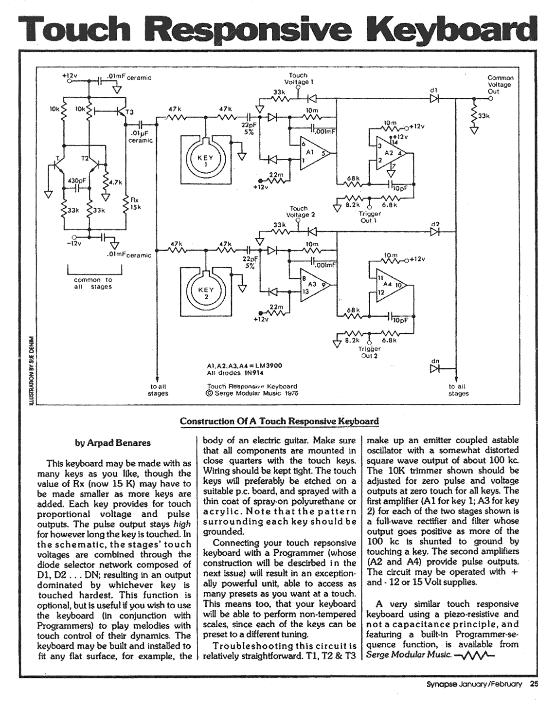
You might look for the Serge TKB schematic. It was a capacitive coupled "keyboard" module from the cult classic Serge modular synthesizer of the 70s and 80s. I did a quick search and couldn't find it, but I believe I have a copy somewhere.

If you can't locate it online, let me know and I'll dig a bit. I don't believe this design used anything esoteric, but it was apparently robust and trouble-free. Serge designs are to analog as Wozniak's are to digital from a similar era: deceptively simple, elegant, and functional.

Cheers,
A P

<edits below>

I can't find the big schematic I remember--it must have been hardcopy. I'll look for it. I did find a couple of things which might be useful. Here's one which may be derived from the Serge design. It was published in the Jan/Feb '77 issue of Synapse. Oh, hey, Synapse in now archived online!

trk2.gif
 
Back
Top