Circa 1966 McCurdy solid-state preamp

GroupDIY Audio Forum

Help Support GroupDIY Audio Forum:

This site may earn a commission from merchant affiliate links, including eBay, Amazon, and others.

ethervalve

Well-known member
Joined
Nov 19, 2008
Messages
211
Location
Montreal
Hi,

I recently acquired a McCurdy PE2600 console and I was wondering if anyone had any experience with these or similar era McCurdy boards? I'd particularly love to hear folks' opinion on the preamp modules (called M26001). Thanks in advance.

McCurdy sold me the manuals and schematics and I asked a tech there if direct outs would be feasible. he said:

As far as direct out is concerned, I'm not sure exactly what you want to do but from a quick look, the electronics seems to run on single ended +33 volt power supplies, most of the internal audio is single ended (not balanced) and the audio transformers are capacitor coupled.
The preamps have low impedance emitter follower outputs capacitively coupled to the transformers. Modification for direct unbalanced outputs should be possible.

Here's a link for the full documentation: http://www.megaupload.com/?d=33UJ8YXK edit: sorry the link died.

This is the schematic:
3253481543_9c52773d26_o.gif


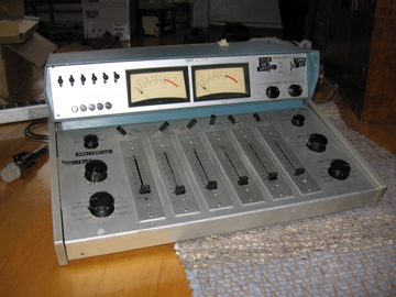
here's the complete console:
3245040170_73a4646d63_o.jpg


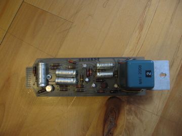
and the pre cards are like this:
3244210131_f95b902535_o.jpg


from sir mix-a-lot's favoured vantage point:
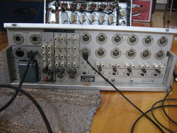
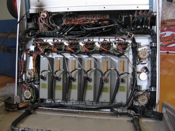
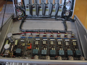
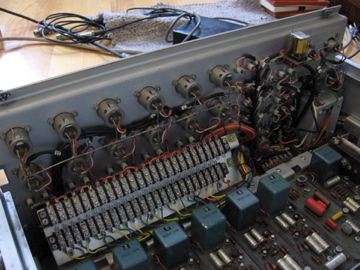
3245037564_43ba6ceb43_o.jpg


innards:
3245037772_5cf326c668_o.jpg

3244210045_e579abe174_o.jpg

3244210287_ff2bb5e55e_o.jpg
 
ethervalve said:
Hi,

I recently acquired a McCurdy PE2600 console for next-to-nothing and I was wondering if anyone had any experience with these or similar era McCurdy boards? I'd particularly love to hear folks' opinion on the preamp modules (called M26001). Thanks in advance. 
Typical of a 1970's not very competent design. Makes me think of Fender or Shure PA's. The input stage is similar to the one patented by Peter Levesley at Audio Developments; the secondary of the input xfmr is actually in the current feedback loop, which has for consequence that there is less noise when the input is open than when it's loaded! A nice feature when you have to deal with a busy broadcast studio. Another consequence is that the input impedance is not as high as one would expect by current standards.
But the real disappointment is in the output stage. The designer has used a Darlington output,hoping its very low output impedance would induce a high output capability. Unfortunately, it is (very) limited by the lack of sink capability by the emitter resistor R17, particularly considering the load of R18; max available current is 0.66mA, which restricts the output level to 4.4V p-p, or ca. +6 dBu . Note that the same problem affects the mic pre in a lesser way.
McCurdy sold me the manuals and schematics and I asked a tech there if direct outs would be feasible. 
You would have to install buffers  or do the mods in order to provide output drive. If I were in your shoes, I would start with improving the output capability; this can be done without affecting the gain structure, which you don't want to tamper with.
a ) swap R17 & 18. That will increase the quiescent current of Q4 to a very conservative 4mA
b ) increase R10 in order to measure ca. 20v at Q4 emitter. This will also increase Q4's quiescent to ca. 6mA. This will also slightly increase the gain, but not that much.
The output capability should now be 20v p-p unloaded (+20dBu). This will still be very dependant of the output load, but if you load it with 10k, you should get a very decent  max output of +15dBu.
There is not much to do to improve the situation with the mic pre, because almost anything done on the output quiescent has consequences on the gain.
I just can suggest adding a resistor from Q2's emitter to ground. Start with 10k, down to 4.7k.
All these mods should be done under the surveillance of an oscilloscope and THD meter!

3253481543_9c52773d26_o.gif
 
ça va de soi but you're a gentleman and scholar.
thanks for taking the time to look at the circuit! (I've filed away your mod suggestions. i've also updated my post at the top and included a link for the full documentation if you or anyone else is curious. 
 
To add a line out for each channel you'll need a line driver for each channel. Here is a schematic from jensen for a single-ended circuit to give you an idea:

http://www.jensentransformers.com/as/as079.pdf

byron
 

Latest posts

Back
Top