Motorized valve repair (radiant heating)

GroupDIY Audio Forum

Help Support GroupDIY Audio Forum:

This site may earn a commission from merchant affiliate links, including eBay, Amazon, and others.

AnalogPackrat

Well-known member
Joined
Apr 12, 2005
Messages
3,408
Location
Far Away From Newsom
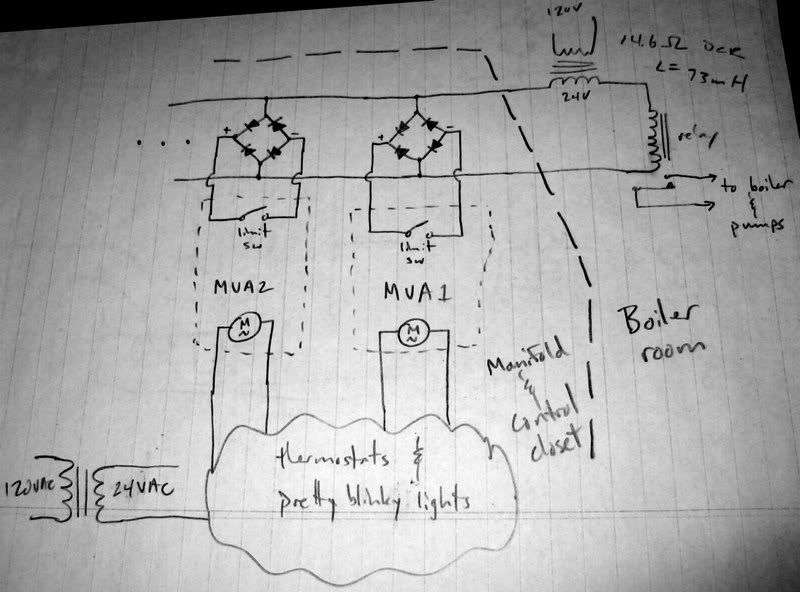
I recently discovered that my 6 year old radiant (hydronic) heating system is acting strangely.  It consists of 5 zones and 7 loops (two zones have two loops the rest have one).  The basic idea is that each zone has a thermostat which controls a valve in the distribution manifold.  When the zone calls for heat the valve(s) for the PEX tubing loop(s) that correspond to that zone are opened allowing hot water to flow.  What's happening is that while all the thermostats are opening their respective valves, the boiler and circulating pumps are not activated until one particular zone calls for heat.

I guess I need to explain the other aspect of the control mechanism--turning on the circulating pumps and telling the boiler that heat is required.  If all the valves are closed in the manifold you don't want to circulate water between the distro and return manifolds for no reason and you certainly don't want your boiler heating water for no reason.  The way this is done is through a set of paralleled switches which control a (remote) relay in the mechanical room where the boiler and pumps are located.  When this relay is closed the boiler does its thing (heating water in a primary loop to the set temp) and the pumps are switched on.

This is all accomplished quite neatly by what are called "Motorized Valve Actuators" which mount on the manifold.  They have a 24AC motor which is switched by the thermostat for the valve's zone.  The motor actuates a plunger via a simple rack and pinion which opens the valve.  The MVA also has a limit switch which closes when the valve is opened.  All of the MVA limit switches are paralleled to the boiler room relay control lines (which connect to either end of the coil of that relay).  I hope that all makes sense.

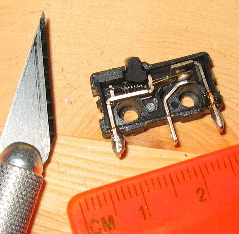
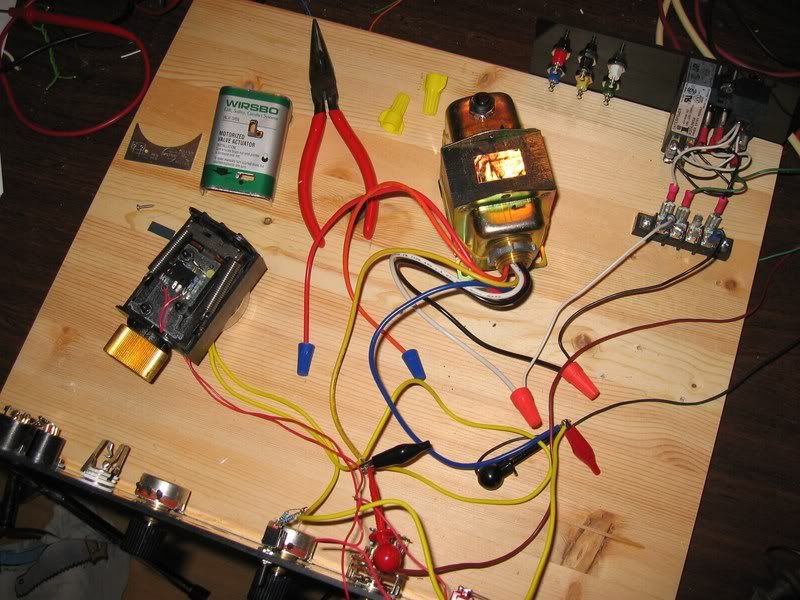
Well, after a little digging online and disassembly I've found that my problem is degraded contacts on the MVA limit switches.  The one I disassembled has a closed resistance anywhere from 15k up to 60k (different value for every actuation of the switch--cruddy contacts).  Open is really open, so it's not a mechanical failure in the switch--just carbonized contacts from arcing.  Here's what the MVA looks like with the cover off.  I'm using my trusty proto panel for the convenient power attachment to my spare 24VAC power transformer.

Fixit2.jpg


And a closeup of the limit switch...

Fixit3.jpg


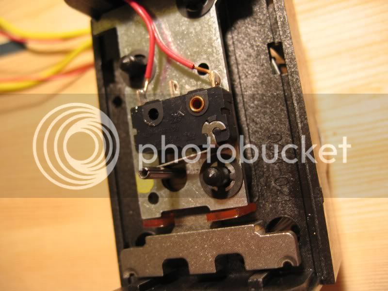
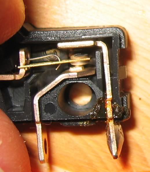
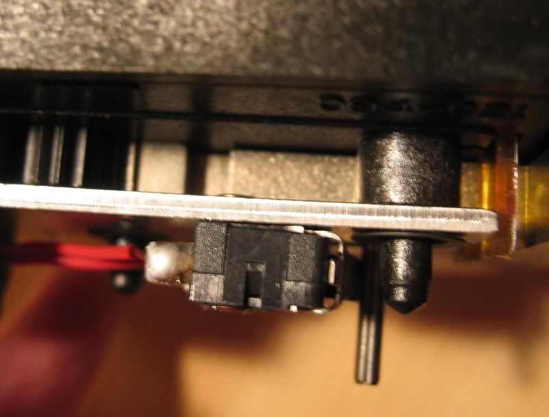
The split-tube thing rides on the plunger mechanism below the metal plate and presses the lever as the valve closes (the NC contacts of the switch are used).  Note the copper pop-rivet which is the only visible attachment mechanism.  There's a short metal stud on the plate that aligns with the other mounting hole in the switch case and keeps it from rotating.  Below is a side view where you can just make out the pop-rivet on the back of the plate.

Fixit4.jpg


So here's the $400 question:  how do I remove the switch?  Replacing 7 switches is on the order of $20 (plus my time at pennies per hour) while each MVA costs $50-60 (and nothing else is wrong with them).  I don't own a pop-riveter, but I could replace the rivets with small machine screws and nuts.  But that would mean removing the plate which is risky.  Those three black studs with the retaining rings are some kind of plastic (polycarbonate) and it would suck to break one.  Any ideas there?  And finally, would using a sealed switch improve the life of the contacts?  Any other ideas to reduce arcing?

Any input is appreciated...

A P
 
While we all know the right answer is to replace it with the factory part.  I would be tempted to MacGuyver it.. I once fixed a similar burnt contact on a dishwasher solenoid back in the early '60s by turning the contact upside down. It was a double throw and open frame, so there was a new contact button on the other side ready to go.

Looking at those limit switches, you should be able to carefully drill out or dremel grind the rivets and replace. ... Or buffer the high Z switch to trigger a sensitive gate triac or relay. If the microswitch is double throw like it looks, maybe use the normally open contact for something clever.

Try not to burn your house down...

JR


Yeah, I'm not opposed to some mild MacGuyvering, but nothing that would risk fire!  I'd rather stay all passive since whatever I do will have to be replicated seven times and the space is quite constrained--there's maybe a cramped 1.5 in^3 in the MVA package that I could try to use.

I neglected to mention the rating was 5A at 125/240V.  Luckily this switch is a common sized package (Omron and Cherry) and I can actually get one with a 10A contact rating which might help a bit with durability.  Of course it is switching some kind of rectified and barely filtered "DC" which is just good enough to drive the remote relay coil.  I imagine the contact abuse is actually occurring when the switch opens--that coil is just not going to like going open and the kick will certainly produce a nice arc.  I wonder if it even has a diode across the coil?  I'd have to go study the setup in the boiler room and do more disassembly there which I would rather avoid.

Thanks for the ideas, John.

A P
 
I don't know if this is any help.  Switches made for 115 and used at low currents and voltages can sometimes carbon up.  Low voltage and current switched should be mechanical cleaning wiping contact or mercury wetted etc. IIRC.  Other switches use the current and higher volt to clean them.  Things like vacuum cleaner switches sometime do not work well in effects

So if I understood the first post could you disconnect the wires and try to switch a current at closer to the contact rating to maybe clean the switch?
 
Interesting idea, Gus.  Yes, the MVA switch connections are easy to isolate this way.  I'm not exactly sure what the switching current is, but I may be able to find out.  Whatever it is it is below 2A because there is a 2A fast acting protection fuse in series with the remote relay line.  The controller board instructions state that the load to be driven is max 1A 24VAC.  Are you suggesting I try switching something like 115VAC using a big dummy load to get a 3-4A current?  Cycle the switch a while and then see what the contact resistance looks like?

Thanks,
A P
 
The post was a guess.  It looks like it is not much current because of the red wire size. I would try an amp at 115 maybe a light bulb?

If you drill the microswitch rivet What might work is something like a rivnut installed in the base plate and a screw to hold the microswitch down.  This will allow you to change the microswitch a few years later when it goes bad again.

Maybe an opto interrupter with a flag on the post what is being switched AC or DC?

Rivnuts are cool thing the problem is you need a tool to install them

found this DIY idea
http://www.fjr1300.info/howto/rivnut-tool.html
 
It's not a PopRivet. That's the kind you don't need access inside the wing for a backup block, there's a through-rod which pulls from the face of the wing.

Whatcha got is a plain old hollow brass rivet.

A 0.2" drillbit in a $9 battery drill will probably take the flare off the rivet. If not, sharp diagonal cutters will chew the flare off. Switch will fall off. I think you have just enough room behind to get the buggered rivet out; if not, push it back and use heavy cutters to shorten it, pliers to round the nip, and push it out.

Going in looks even easier. Plenty of room behind for a nut. You will need forceps or needlenose to hold it while you start a machine screw through the switch hole.

You may also be able to find a J-nut which will slip over the side of the steel plate.
J%20nut%20Design%20Variations.png

http://www.abcorfasteners.com/J%20Nuts.htm
Hardware shops often have a bin of these. The extra 0.02" of metal probably won't matter. The one-thread engagement is weak but your switches are not violent.

Are these SNAP switches? Or do they just kiss the contacts? The original MicroSwitch (like PopRivet, a pioneering brand) were snap switches, and known to take good abuse. If these are kiss switches, and break lingeringly on a slow-motion screw motor, then yes a 2A inducty load is sure to burn "5A" contacts, though maybe not within your 30-day system warranty. If you got 5 year warranty, then someone did his sums VERY well.

Have you worked the lever with your finger instead of trusting the motor? If they are non-snap switches, the tolerances may be giving "just barely" contact. Bending the lever may get "good" contact.

The MicroSwitch size is industry standard. Start with a Major brand, then look for a lever similar to yors (but not that cheezy slip-hook pivot!), and 5A rating should be good
 
The wire is 18ga.  I'll try the higher voltage switching tomorrow--getting ready to go visit the neighbors this evening.  Rivnuts are also neat, but it looks like the smallest size is M3.  The hole in the switch is 0.1" (M2 will fit) which means the hole in the plate where the rivet is fastened is also about 0.1".  If I could find an M2 rivnut, that would be interesting, but I imagine that's impractical to make.  I was thinking of fastening the replacement using an M2x15mm machine screw if I can find a few in my junk bin or at the local HW store.

Yeah, a light interrupter or hall effect device driving a solid state switch would be better.  I had the thought that it might not be that hard to make the SS switching external to the MVA units.  I need to take a closer look at the "control module" which is a pair of ganged PCBs that connect everything and provide pretty indicator lights for each zone.  The only thing on the PCB other than a plethora of screw terminal connectors is a fuse per board, current limiting resistors for the LEDs, a diode per zone and a small bridge rectifier per zone.  Nothing else.  No caps, no other resistors, etc.  So I'm trying to figure out what the bridge is for.  The motors are 24VAC, the output drive is supposedly 24VAC.  Weird.

Thanks for the thoughts,
A P
 
PRR-

Yes, I believe they are Snap Switches--definite click when you reach the switch point.  I have fiddled the lever manually (is that legal?).  I had to remove the springs which force the valve closed when power is lost (the motors fight against this to hold the thing open), but they are easy to re-assemble.

Tomorrow I will sacrifice this one unit in the name of engineering.  First I'll try Gus' idea and if that doesn't help I'll drill the flare off of the rivet and remove the switch. 

Thanks for the HW pointers.  I'll look for the j-nuts as well.

A P
 
Update time.  I tried Gus' idea and hooked up a 60W (and later 75W) incandescent to the MVA that I had on the bench.  It would usually switch but not every time (despite the positive "click" sound)!  And the nasty arcing sounds coming from inside the switch were not comforting in the least.  I guess I cycled it maybe 20 times.  No improvement--if anything it seemed to get worse.  After pulling the apparatus apart I measured the contact resistance and it was much higher.  Oh well.  It was toast anyway.  Worth a shot.

I have temporarily swapped the two MVAs that work to the master bedroom zone so my wife can stay warm while I'm out of town after this week.  Repair will begin when I return.

I also traced the control PCB circuit.  The main part I was curious about was the limit switch side--the motors and indicator lamps work, so I didn't show all of that.  Below is the schematic.  I just showed two zones and I forgot the fuse on the upper left (where the control lines exit the manifold and control closet and go to the boiler room).

fixit_schematic.jpg


Note how the boiler room side has another 24VAC transformer with the relay coil in series.  The way the bridges are used is funky.  All switches open and no current flows in the big AC loop.  Any switch closes and current flows with the switch taking what looks to me like current only limited by the DCR of the relay coil and transformer (I measured these at 14.6ohms).  What happens when more than one switch closes?  I have a suspicion that the one with the lowest bridge diode voltage drop takes all the current.  This switch is the first to fail...then the next lowest start to take the load...continue until all switched have failed.

So what can I do to improve the life of the switches after I replace all of them?  Note that any "fix" which assumes polarity of the the limit switch wiring will be a problem as they are now polarity ignorant (and both red).  I could swap one of the wires for white when I replace the switches but any future hydronic fixer guy is going to be very confused when he sees it.  I guess since the relay is AC there's no good way to snub the inductive kickback when the last switch goes open.  Or did I get that wrong?

If there was some easy to implement and compelling design I suppose I could just bring all the limit switch wires out to a separate board and not use the part of the controller PCB that handles the relay switching.  If there was a way to use the undamaged NO contacts of the switch that would be special.

Anyway, there it is for those of you that are interested.  I plan to order the new switches from DigiKey or Mouser tonight or tomorrow at the latest.  I'm heading out of town for work at the end of the week so I'll need to jump on the fix as soon as I return.  Thanks again for all the great ideas and pointers so far.

Cheers,
A P
 
OK, I drilled out the rivet and popped the switch off.  Had to open it up to have a look.  Lots going on in a tiny space:

switch_guts1.jpg


And here I'm holding down the button so you can see the carbonized NC contact.  The macro capability of my old Canon s400 Digital Elph still blows me away.

switch_guts2.jpg


Would a basic RC snubber across the switch help?  Something basic like 100R in series with 100nF?  I could either tack it to the terminals at the switch or plug it into the terminal block with the switch wires.

A P
 
I think you can just use a cap without R but I'm not sure how to size it. When switching AC it will leak current all the time so not so big that it leaks significant current.


JR

BTW from looking at that switch insides it reminds me of the dishwasher switch I fixed decades ago. Flip the contact bar upside down, emory file the top contact and you're ready for a few more years of action.
 
You know, when I first read your post I thought "are you crazy?  Didn't you see the scale?"  But in about 5 minutes I did exactly that and now read 8mOhms (using Fluke 8800A) on the repaired contact.  It's tempting to just do this to all of them, add snubbers, and call it a day.  I'll think on it one more night--tomorrow is HW hunting season.  New switch or old switch--I have to be able to mount the things again.

Thanks,
A P

p.s.  Reminds me of the time around 1979 or so when my Dad's Marantz receiver's power switch quit working.  It was a push-push spring loaded type.  We took the unit apart and pulled the switch.  Then we took the switch apart and found the spring was broken.  We removed the pieces and finagled a longer plastic post where the button was and viola--push-pull power switch.  It worked for at least another 10 years like that.
 
> So I'm trying to figure out what the bridge is for.

Someone was confused.

It is an AC relay and agnostic switches.

The rectifiers are pointless.

I would presume there is an alternate zone motor with an SCR switch, polarity matters.

> any "fix" which assumes polarity of the the limit switch wiring will be a problem as they are now polarity ignorant (and both red).

The screws they go to are both red? Or are they polarity marked?

With an SCR or Darlington, you could put milliAmps through the contacts and get your 2 Amps to the relay. But then polarity matters.

(Oh: and over-clever topology would allow using the NO contact... but as John pointed out, these gizmos are sometimes easier to flip than to replace.)

If I ran the industry, those loop would be AC, bridges would be in the zone-valve -if- it were a DC switch. That's how my very simple steam heat runs: 24V AC valve, usta be mercury switch upstairs, now it is a CPU with a bridge facing the AC side to make DC for the CPU and battery back-up.

Try this. It leaks ~~0.024A through the boiler relay, perhaps not enough to turn it ON or delay dropout when it should go OFF. However when the last zone-switch goes OFF, the coils try to kick-up 200-some volts into the open circuit, which won't happen so much into 1K resistor.

2vry92a.gif


And I still wonder if the problem isn't just junk switches. These really "should" take 24V 2A breaks for years. And the carbon-soot is a sign of oil or other carboniferous contamination. You got an oil leak? Smell gas? Do a lot of carb-cleaning around the switches? True, it can be stray rug/paper dust burning on the metallic contacts. And yes a BIG arc will broil carbon from the plastic shell. Or it could be factory oil. Even lunch-oil on worker fingers, which means only the first tray of contacts after lunch is short-life.
 
PRR-

After tracing the "output" side of the circuit as shown I better understand the bridges.  No, the limit switch terminals on the control PCB are not marked with polarity (even though it is there and known).  The switch wires on the MVA unit are both red.  Both the MVAs and the control unit are from the same manufacturer, so this was intentional (ease of installation I would assume).  I believe the "boiler on" indicator LED may also be connected across the FW rectified AC.  On the worst zone, this LED is dim and flickers a bit which would make sense if its limit switch is arcing.

The motors are fed 24VAC and are powered from the manifold closet transformer (bottom left of my diagram).  The connections are unpolarized and motor wires are both yellow. If there is any SCR stuff going on it is in the motor side of the MVA housing and I haven't cracked that open.  I haven't finished tracing the thermostat/motor control part of the PCB (trying to do it in-situ is tricky)--it's the cloud in the diagram.  Note the galvanic isolation between boiler circuit and thermostat/valve circuit.  No ground loop issues.  Simple to make safe and reliable.  Plumber proof.

I can easily try the 1k 2W idea.  Have to get the scope off the bench and near the closet to check for signs of arcing.  A friend suggested a more complicated snubber with a small cap in parallel as well as a resistor in series with a diode (polarity!) also in parallel.  Any thoughts on that?

The switches may well be cheap junk.  I don't recognize the logo, but on the back side they are marked MICRO.  Never heard of it.  If i replace them it will be with Omron 10A models at a couple of bucks a pop.

Thanks,
A P
 
I'm not sure how to apply diodes with AC windings. A small C shunting across the switch contacts should be simplest. Small R in series with C if dealing with very serious current spikes. If C is too large it could prevent relay from releasing, or cause it to chatter (bad).

re: "micro" I though "microswitch" was the name of the brand or company that pioneered those style switches.

JR
 
On the C || R-Diode snubber I meant to say "across each switch" where polarity is defined (though not labeled on the terminals).  Obviously that won't work on the AC side of the bridges.  Sorry for the confusion.

Honeywell owns "Microswitch" now and the switch I have doesn't look like the ones in their web catalog.  In particular the labeling and the lever assembly are different.  The lever on mine is rather flimsily done--it snaps on over the case which has molded-in axle bumps and angular motion stops.  The better ones seem to have the lever entering the top of the case...

A P
 
> a more complicated snubber with a small cap in parallel as well as a resistor in series with a diode (polarity!) also in parallel.

That's for DC.

For AC, the next step after a medium resistor would be a low-value resistor in series with a capacitor. The low resistor WILL kill the kick... but would leak a lot of current, heat, and in this case the "off" relay would stay on all the time. The capacitor is sized to load the kick without leaking a lot of 60Hz current. 10r plus 0.1uFd seems to be a common combination. I'm leery of caps in pulse work because they fail without warning or smoke.

I still think those diode bridges are pointless, and a potential failure. If kick is burning contacts, what is it doing to tiny junctions? If the right diodes blow short, the burner runs all the time; blown open, that zone can't call for burner and circulates cool water until another zone has demand.

Steam heat is not perfect; and I only have the one thermostat. But every time I see the complexity of even a "simple" zoned system I wonder if it is worth it. I make fire, steam rises to three corners of the house (you never have all the air-valves working at once), it gets warm all over.

You could add a "small" relay to sense the zone switches and power the boiler relay. But you already have too many contacts having problems.
 
PRR said:
> a more complicated snubber with a small cap in parallel as well as a resistor in series with a diode (polarity!) also in parallel.

That's for DC.

Well, rectified AC means the + end of the bridge is always >= the - side.  So the diode-R works on the switch side of the bridge, doesn't it?

For AC, the next step after a medium resistor would be a low-value resistor in series with a capacitor. The low resistor WILL kill the kick... but would leak a lot of current, heat, and in this case the "off" relay would stay on all the time. The capacitor is sized to load the kick without leaking a lot of 60Hz current. 10r plus 0.1uFd seems to be a common combination. I'm leery of caps in pulse work because they fail without warning or smoke.

That's my preference (series RC).  I can get ~100nf high voltage caps cheap at local surplus joints (if I don't have some stashed already from previous visits).  A failed cap will result in me being right back where I started but with a 2015 calendar.

I still think those diode bridges are pointless, and a potential failure. If kick is burning contacts, what is it doing to tiny junctions? If the right diodes blow short, the burner runs all the time; blown open, that zone can't call for burner and circulates cool water until another zone has demand.

I haven't given you all the info--there may yet be a connection with the "boiler switch closed" LED indicator for each zone.  I haven't completely traced the blinky light part of the PCB.  I might just have to do it to satisfy my own curiosity.  As for failures--I read it differently.  First, the boiler room relay controls the boiler (which is commanded by its own water temp thermostat) AND the circulation pumps.  If the right diodes blow short, the system is stuck "on" even if no zones call for heat.  So the pumps run, but the boiler cycles on and off keeping about 1 gal of water at 160F (inner circulation loop is short) in well insulated piping.  There are no heat losses into the house. 

Blown open means the affected zone cannot control the pumps/boiler, but it can and will open its valve, so when another zone calls for heat, it gets it as well.  This is effectively what is happening now as I have only one zone with functioning limit switches.  Since the switches are failing and the bridges carry on, I'm not too worried about the little junctions.  I'll check to see if there are discernable PIV ratings or part #s on them.

Steam heat is not perfect; and I only have the one thermostat. But every time I see the complexity of even a "simple" zoned system I wonder if it is worth it. I make fire, steam rises to three corners of the house (you never have all the air-valves working at once), it gets warm all over.

Yeah, well, until now I've been very happy.  Our system is retro-fit tubing on floors type.  The temperature into the supply manifold is 120-130F.  I keep the room thermostats (5' off the floor) set to 65-66 when we're home.  Because the floor is warm you don't get the big temp gradient like most heating systems (e.g. scorched air).  Your feet feel warm and you feel warm even though the air isn't really that warm.  I like it.  If you have carpets or lots of rugs it's not such a good thing for obvious reasons.

You could add a "small" relay to sense the zone switches and power the boiler relay. But you already have too many contacts having problems.

No argument there.  I need a simple passive solution to kill the spikes.  I see no reason I can't implement both the 1k 2w across the AC and little RC snubbers at each switch.  That should buy me some more contact life.  Those motors will probably die next...

Thanks again for the discussion,
A P
 
I have been thinking about this and I think PRR's post about the switch maybe being "junk" or having oil or dirt or just not a good one might be the problem.  The description sounds like a outside intake and vent weil mclein with the 1 gallon.
  I drew up a low RDSon power mosfet and photovoltaic optoisolator having the stock switching turning on the optoislators LED(The kind with photocell that generate voltage to turn on the mosfet(gate to source voltage))  Problem would be the supply for the LEDs and keeping the sections isolated.  The switch would only need to supply the LED.
 

Latest posts

Back
Top