2254C build/support thread

GroupDIY Audio Forum

Help Support GroupDIY Audio Forum:

This site may earn a commission from merchant affiliate links, including eBay, Amazon, and others.
Hey Guys,

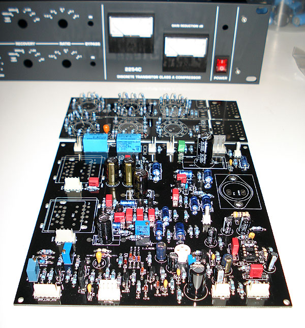
Well I'm making progress!

2254C_Case.jpg


2254C_PCB.jpg


I still have a couple questions I'm hoping for some help with.

1. I'm struggling to find a 310R resistor for the COM-MKUP stage, I assume a 300R will be fine?
2. R41 on the PCB shows 1K5, though the BOM shows 1K2, which is correct?
3. How are you guys testing your 4153 diodes for matching? Igor recommends they are matched, just wondering how you are doing so?
4. RE transformers, I'm using the Carnhill replacements for the old Marinairs, I assume T1 is the LINE INPUT and T2 is the MIC INPUT used as the interstage transformer?
5. What are the extra 'trano' PCB's for on the the control board PCB's, they have no solder sides?
6. RE both the PSU and 2N3055 Heatsinks, does one need to use a mica insulator on either or both?
7. I know that is was answered a few posts back, but RV1, the 5K trimmer, I can't find the part number used on the BOM, so will use a standard trimmer, but there seems to be an arrow pointing to the 3 on the PCB silkscreen, what is this for/indicate?

Thanks in advance!

Regards

Matt
 
1. I'm struggling to find a 310R resistor for the COM-MKUP stage, I assume a 300R will be fine?
Yes, 300r will be fine.
2. R41 on the PCB shows 1K5, though the BOM shows 1K2, which is correct?
R41 is output transformer's load. It can be in range 620R...2k, I used to use 1k2. 1k5 will work fine as 1k etc.

3. How are you guys testing your 4153 diodes for matching? Igor recommends they are matched, just wondering how you are doing so?
By measuring Vf with multimeter, diode mode, don't touch the diodes with fingers (Vf changes from temperature).

4. RE transformers, I'm using the Carnhill replacements for the old Marinairs, I assume T1 is the LINE INPUT and T2 is the MIC INPUT used as the interstage transformer?
Yap :)

5. What are the extra 'trano' PCB's for on the the control board PCB's, they have no solder sides?
Put this under transformers to avoid shorts if trafo's fitted on PCB.

6. RE both the PSU and 2N3055 Heatsinks, does one need to use a mica insulator on either or both?
Nope, no need for mica/insulator.

7. I know that is was answered a few posts back, but RV1, the 5K trimmer, I can't find the part number used on the BOM, so will use a standard trimmer, but there seems to be an arrow pointing to the 3 on the PCB silkscreen, what is this for/indicate?

Standard 10 or 20 turns trimmer, 5k, Bourns etc. Hmmm....arrow came from Eagle standard package. Dunno... :)
 
While we're on the subject of that sort of thing...
There's a few 80uf caps on the board but not on the BOM, I assume it's cool to use 100uf here.

 
Igor said:
4. RE transformers, I'm using the Carnhill replacements for the old Marinairs, I assume T1 is the LINE INPUT and T2 is the MIC INPUT used as the interstage transformer?
Yap :)

you can actually swap the traines, it doesnt harm the circuit... you get different gain structure, much harder to calibrate ... i am using one mono unit like that, with extra ba283 board on the input for more drive...  especially on low level signals it blows ur mind away ...
try on your own risk tho....

 
I feel like this is going to be obvious, but i can not sort out the stereo/dual mono switch. I have no idea where those controls are on the PCBs. Otherwise, things are looking up! i am testing the audio tonite! This discussion has been very helpful!

Cheers
 
can you see then "link" on control pcb ... you just put a switch to that, and connect to second unit...
when they short, its stereo... when they are no-short dual mono

EDIT : hope you matched your diodes an both units...
 
Igor,

Thank you VERY much for all the info, no doubt it may prove useful to others who are providing their own parts rather than using the kit option  ;D

VERY clever on the trano standoff's, I must say it is VERY clear now, but I scratched my head a bit at first  :p

RIGHT! RE transformers. I have mounted the standoff PCB and was just about to solder them and it dawned on me that one can VERY easily screw things up but fitting the transformers the WRONG way round on the board as if you flip the tranos, at least the Carnhill/Marinairs you can quickly reverse the windings around  :eek:

I threw this drawing together from the Carnhill application guide that Colin has on his website that may prove useful to others as desoldering these tranos from a DS board would be a nightmare!

Carnhill_Tranos.gif


The drawing doesn't indicate the primary vs secondary windings but is it safe to assume the 2+4 and 3+5 windings are the PRIMARIES? Can anyone confirm?

Here is the Marinair one as a reference:

DSCF1997.JPG


Likewise looking at the PCB here:

2254C_PCB_.gif


It seems T1, in this case the LINE INPUT, or VTB9046/10468 goes in with the PRIMARY facing the RIGHT TOWARDS the 2N3055, correct?

It also seems T2, in this case the MICROPHONE INPUT, or VTB9045/31267 goes in with the PRIMARY facing the LEFT AWAY from the 2N3055, correct?

I know these seems like silly questions/statements, but I know that someone, somewhere WILL make this mistake and so posting it here in the open helps future builders.

Cheers

Matt
 
its very confusing to indicate tranie directions via tranies facing side...
pin numbers are clearly marked at the bottom of the tranies... its better of use them as reference point.

if you solder carnhills to pcb you will need 2u unit for mono, as they are pretty tall...

its very easy to get confused with tranies... and if you make mistake it will be pain to de-solder them...
i would use molex connection provided, they are clearly marked, if you make mistake, very easy to recover...
molex connection instruction for transformers are covered earlier in the theread...


kambo said:
its very confusing to indicate tranie directions via tranies facing side...
pin numbers are clearly marked at the bottom of the tranies... its better of use them as reference point.

if you solder carnhills to pcb you will need 2u unit for mono, as they are pretty tall...

its very easy to get confused with tranies... and if you make mistake it will be pain to de-solder them...
i would use molex connection provided, they are clearly marked, if you make mistake, very easy to recover...
molex connection instruction for transformers are covered earlier in the theread...

Hi Kambo,

All good points, but in the case of a 2U rack it makes sense to mount them onboard as it safer in that they cannot break off/move around and if we know for a fact the pinouts displayed here are correct then it will be easier for other builders in future.

RE the sides, I indicated PRIMARY sides in both cases, but it makes the assumption that PIN 2+4 & 3+5 are indeed the PRIMARIES (awaiting confirmation from anyone in the know).

Cheers

Matt

EDIT: Using my multimeter set to DC resistance I get the following on a VTB9046

Pin 2+4 = 180.4R
Pin 3+5 = 180.4R
Pin 7+9 = 62.4R
Pin 8+10 = 62.4R

Safe to assume Pin2+4 and 3+5 are the PRIMARIES?
 
Hi
    what is the power transformer rating(2ch.)? Also, I'm about to start design for the front panel and looking at Igor's front panel I've noticed that Lorlins stop at position 11? They don't go all 12 steps?

Thank you
 
Power trafo rating is 25-30 VA. This was already discussed on this thread :)
Lorlins are stoped at 11. If you need Corel file to to adapt it to your own design,
please pm.
 
Thanks Igor. I've must overlooked it somehow, two times, as I re-read the whole thread today , again ;)

 
Hi Guys

Can someone advise on how to link the two compressors together for stereo bus mode ?
There is a Link pad on the main board which looks to goto Front Panel (from circuit diagram)
I'm trying to understand where the link switch on front panel comes into play and what connections to make ?

Many Thanks
John
 
John, just go back to page 12 :)

http://www.groupdiy.com/index.php?topic=32605.msg438089#msg438089
 
just to clear this thing for me...
the only 2x6 lorlins are for com_recov and hpf, all others are 1x12. right?
and R´19 on the com_mkup should be left free?
cheers, alex
 

Latest posts

Back
Top