You are using an out of date browser. It may not display this or other websites correctly.
You should upgrade or use an alternative browser.
You should upgrade or use an alternative browser.
2254C build/support thread
- Thread starter Igor
- Start date


Help Support GroupDIY Audio Forum:
This site may earn a commission from merchant affiliate
links, including eBay, Amazon, and others.
haima
Well-known member
looks great!
how's it sound?
if you get a chance to do some sound samples - lets hear it!
cheers,
haima
how's it sound?
if you get a chance to do some sound samples - lets hear it!
cheers,
haima
user 10827
Well-known member
- Joined
- Sep 21, 2007
- Messages
- 786
fantastic! ;D
substitute
Well-known member
good gravy, I finally tried to fire mine up tonight and I got nothing, nothing at all. Voltages seem ok, but nothing in bypass no sound no way. I'll go over all the wiring and parts placement, but man am I depressed now.
I feel like there's something big I'm not getting, what is CV? What is CCV? I see those points on the power supply and reading through the thread I've picked up that I should alligator clip them to the control board for testing, but do they play a part in normal operation?
Looking at the schematic I'm pretty confused, mostly by the relays. It's a new concept to me and I don't understand their function, I figured I didn't have to since there was only one way to put them on the board.
If some one could explain those things to me that might be a start, other wise I'll keep digging and asking til we hit on something.
ur unit should pass audio even without any power...
relays are set to be in bypass mode when power is off, or bypass engaged...
relays routes audio to the circuit only when comp engaged...
you should hear some very very low switching noise from relays when you in/out your unit.
that tiny switching noise is more noticeable if you turn off your unit, while ur unit is engaged to compress (red led's are on)
ccv counterclockwise
cv clockwise
those connections with alligators are only for calibration purposes...
EDIT : that switching noise i am talking about from relays are mechanical noise not click etc kind of noise.
substitute
Well-known member
interesting... I'll spend some time with it tomorrow, thanks for the tip about passing audio regardless of power. I really think I've overlooked something hugely obvious. Sadly, my camera is pretty junky but I'll see if I can get some decent pics going.
substitute
Well-known member
Ok, so I spoke a little too soon. I had the 2254 set up on an insert on my mixer (which I've done with all my other builds) and was getting complete silence, when I went directly from a mic pre to the compressor voila!
I noticed this on the 33609 page...
I'm not sure what that means, or if it has anything to do with the 2254 boards, but my wiring from the main board is...
1 ground (pin1 on xlr)
2 + (pin2 on xlr)
3 - (pin3 on xlr)
seems pretty straight forward, but I don't want to assume anything, plus the complete silence on the insert really makes me think something was shorting to ground.
now I just need to sort out that test procedure...
I noticed this on the 33609 page...
Errata: If you look at the signal output, on the right of the pic called "33609_SCHEM_VOLT.jpg", the numbers differs from the PCB.
1 HI
2 GND
3 LOW
THIS IS CORRECT...
I'm not sure what that means, or if it has anything to do with the 2254 boards, but my wiring from the main board is...
1 ground (pin1 on xlr)
2 + (pin2 on xlr)
3 - (pin3 on xlr)
seems pretty straight forward, but I don't want to assume anything, plus the complete silence on the insert really makes me think something was shorting to ground.
now I just need to sort out that test procedure...
substitute
Well-known member
Thank you, just to set the record straight that would mean pad1 on pcb is xlr pin 2 and pad 3 is xlr pin 3, right?
More importantly how did everyone else know this? I like to know why I make a mistake.
and by the way, Kambo, I vote you MVP on this project. Cheers!
More importantly how did everyone else know this? I like to know why I make a mistake.
and by the way, Kambo, I vote you MVP on this project. Cheers!
Most gear is pin2 (+) nowadays, which is probably what folks are going off of. That leaves pin1 as ground and pin 3 as (-). So, with that knowledge of the "standard" in hand, you can proceed with connected the (+), (-) and grnd pads to whatever you need. If, for some reason, you're running a pin3 hot system, you would hook pin 3 as + and pin 2 as - . Sorry if you already knew all that, but I thought that it might have been the unmentioned standard that you may have missed. Congrats on the build!
ben
ben
substitute
Well-known member
Thanks bd, I wrongly assumed that pad1 on the pcb meant pin1 on the xlr and so forth. Looking back at the schematic now, I can see how it's labeled. So I switched around my wires and did some calibration and things are sounding pretty nice. I still need a proper scale for the meters and need to drill a bunch of holes in metal but I'm nearing the finish line. The low end on this thing is bananas, big giant bananas!
Cool. If you need Corel front pannel drawing (easy can be converted to .plt's to use with Front Pannel Designer)
and meter's scale, just PM me with request and your mail address.
@Kam: Thanx!!! You're fast as lighting! BTW, what is MVP?
HNY to all you, folks!
")
and meter's scale, just PM me with request and your mail address.
@Kam: Thanx!!! You're fast as lighting! BTW, what is MVP?
HNY to all you, folks!
BTW, thanx to Jplum, very fast and easy calibration procedure:
Pot nR's are equiv. to 33609
Feed 0dbV or 1V RMS 1 kHz measured between pins 2 and 3 on input XLR with AC voltmeter;
Disconnect THR Molex connector from mother board
Connect THR Molex connector on mother board
Yap.
Pot nR's are equiv. to 33609
Feed 0dbV or 1V RMS 1 kHz measured between pins 2 and 3 on input XLR with AC voltmeter;
Disconnect THR Molex connector from mother board
- I set Pot on PSU to give 3v at +CV and -CV on PSU
- Adjust gain pot to get unity gain with unit Bypass In
- I croc clipped +CV from PSU to Link on main board
- Adjust RV2 to get -8db at output XLR
- Adjust Pot on PSU for -20db at output
- Adjust RV3 for 20db on meter
Connect THR Molex connector on mother board
- Put threshold to -2db (1st click)
- Adjust RV5 for -1db at output
- Put Threshold to -20db and measure -16db (ish - slightly less in fact on my unit)
Yap.
Igor said:@Kam: Thanx!!! You're fast as lighting! BTW, what is MVP?
HNY to all you, folks!
hehe
MVP : i suppose Most Valuable Person ;D
i might be totally wrong tho...
happy new year to you all....
substitute
Well-known member
BTW, what is MVP?
Most Valuable Player, it's an award in baseball.
Igor, I got the scale and layout docs from you yesterday. I drilled my front panel today, some things got a little wacky so my layout will be a little different than most folks but I'm comfortable with that. I made a pretty cool jig for cutting the meter holes, I'll post some pics once I get it all buttoned up.
When you printing from Corel, it is important to know the scale is correct.
You can print 100x100 mm rectangle and check the measures.
Or, when converting to HPGL etc, sometimes measures comes wrong. For me, 1016 HPGL format works best.
Will be happy to see pictures.
Happy New Year!
You can print 100x100 mm rectangle and check the measures.
Or, when converting to HPGL etc, sometimes measures comes wrong. For me, 1016 HPGL format works best.
Will be happy to see pictures.
Happy New Year!
substitute
Well-known member
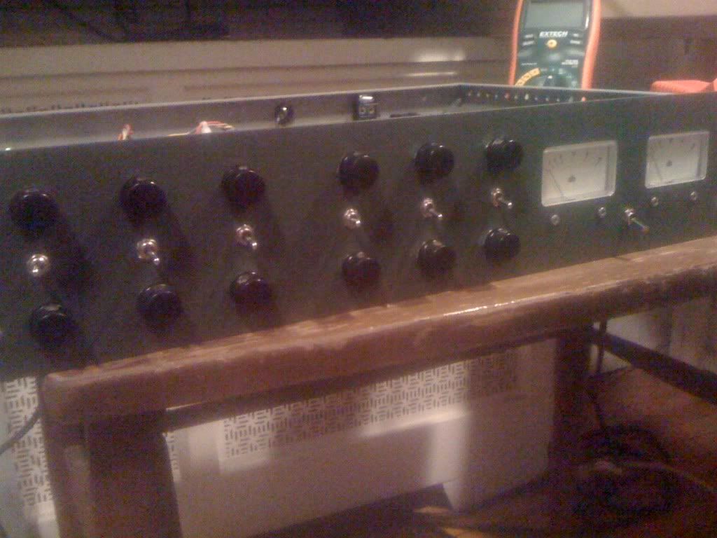
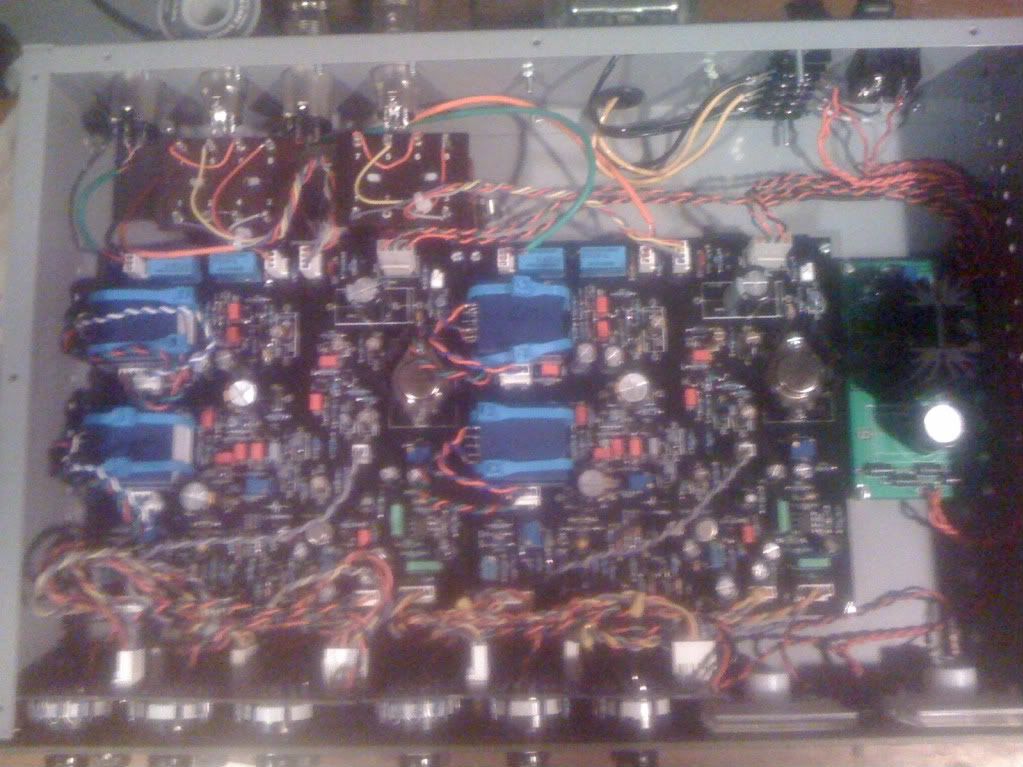
all buttoned up and calibrated...
here's some pics of my jig for cutting meter holes...
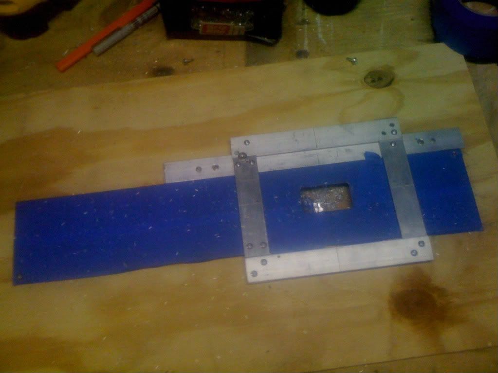
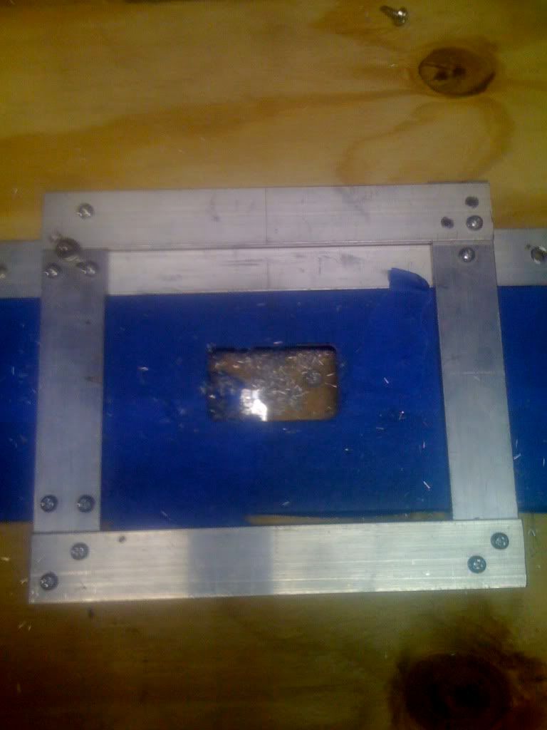
I used a Rigid laminate trimmer with a freud "all carbide bit" from home depot. It cut very nicely, now if I could just build a decent digital camera.
here's some pics of my jig for cutting meter holes...
I used a Rigid laminate trimmer with a freud "all carbide bit" from home depot. It cut very nicely, now if I could just build a decent digital camera.
Similar threads
- Replies
- 192
- Views
- 75K
- Replies
- 14
- Views
- 6K