You are using an out of date browser. It may not display this or other websites correctly.
You should upgrade or use an alternative browser.
You should upgrade or use an alternative browser.
2254C build/support thread
- Thread starter Igor
- Start date


Help Support GroupDIY Audio Forum:
This site may earn a commission from merchant affiliate
links, including eBay, Amazon, and others.
substitute
Well-known member
it's all the normal controls, I made some weird assumptions about where I should place the meters so I had to compensate and move the switches around.
Soldering switches directly to boards makes me really paranoid, I never seem to get all my holes exactly right. I'm getting a lot better at metal work but I still like to give myself some wiggle room.
Soldering switches directly to boards makes me really paranoid, I never seem to get all my holes exactly right. I'm getting a lot better at metal work but I still like to give myself some wiggle room.
ultra-alex
Well-known member
substitute said:all buttoned up and calibrated...
nice one substitute! i also like to arrange my main pcbs next to each other instead above. i saw you placed the mains torodial outside the case!?
is this the better way or can i proceed as planned in the picture below?
happy new year! cheers, alex

substitute
Well-known member
i saw you placed the mains torodial outside the case!?
is this the better way or can i proceed as planned in the picture below?
I didn't use a torroid, just a regular transformer. It's shielded, but i wanted be sure, so I mounted it outside the chassis. That, and I ran out of room in the case. I've never had a problem with a torroid in a case.
maybe smaller switches in future!
That, or I could just get my act together and start measuring correctly.
")
substitute
Well-known member
yeah, I know, I got the template from you but I had already cut the meter cut outs. The right hand side of channel two slightly hangs over the back of the meters, so the switches wouldn't fit on the board. I didn't want to start over so i thought I'd see if I could make it work.
I want my projects to look kind of hand made, not like stuffed in a shoe box with a bunch of electrical tape, but not like they came from guitar center either.
I also have an aversion to words, lights, and (I'm getting over it) meters...
I want my projects to look kind of hand made, not like stuffed in a shoe box with a bunch of electrical tape, but not like they came from guitar center either.
I also have an aversion to words, lights, and (I'm getting over it) meters...
matta
Well-known member
Success, well kind of!
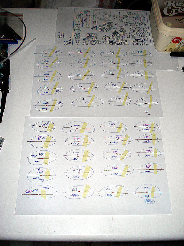
I finally finished up the 5 x 2254c boards last night, just ahead of power up I had fun matching the diodes and setting out to wire up:
I then wired up my single channel unit to test all the main boards in as it was easier to troubleshoot.
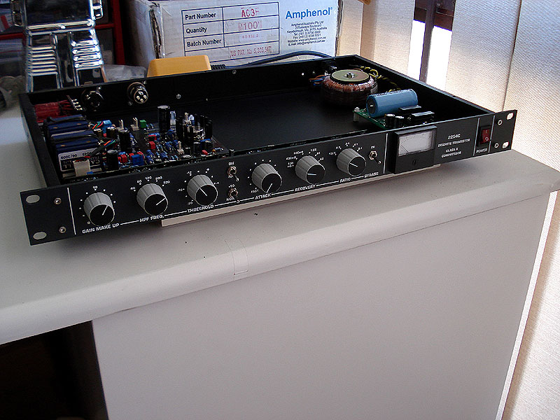
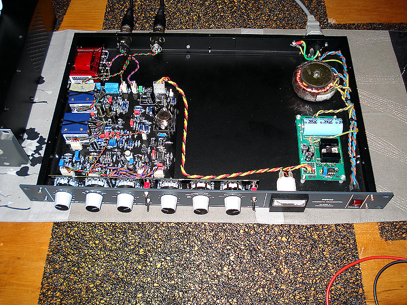
Now the completed wiring, awaiting testing (will neaten it up more when I have calibrated them and am ready to close the cases). I powered them each up, no smoke, passing audio, half the battle won!
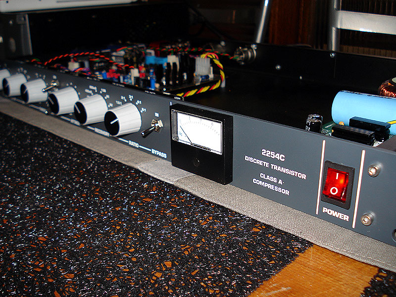
And a nice close up of the front panel.
The problem is a LOUD hum, which I think has to do with my grounding scheme, in BYPASS the comp is as clean as a whistle, when engaged there is a loud hum, the controls all work as they should and it passes audio fine, but passes the annoying hum as well.
I'm thinking it either power supply or wiring related as it happens on all 5 boards, it could be control board related as I used the same board for testing each unit.
I've made a minute sample here, starts off with the said hum, then some audio that I mucked about with with the various controls and at the end you can hear the hum disappear as switch between bypass and engage.
2254C Audio Sample (5MB)
My grounding scheme is as follows:
IEC ground to Chassis
From that ground point I ran a wire to the solder pad on the 2254C PSU, which is linked the CHASSIS ground tab on the PCB
From the I followed the convention of the dual grounds to the main board, with the +24V and the CHASSIS ground.
Am I missing something?
Thanks in advance!
Cheers
Matt
I finally finished up the 5 x 2254c boards last night, just ahead of power up I had fun matching the diodes and setting out to wire up:
I then wired up my single channel unit to test all the main boards in as it was easier to troubleshoot.
Now the completed wiring, awaiting testing (will neaten it up more when I have calibrated them and am ready to close the cases). I powered them each up, no smoke, passing audio, half the battle won!
And a nice close up of the front panel.
The problem is a LOUD hum, which I think has to do with my grounding scheme, in BYPASS the comp is as clean as a whistle, when engaged there is a loud hum, the controls all work as they should and it passes audio fine, but passes the annoying hum as well.
I'm thinking it either power supply or wiring related as it happens on all 5 boards, it could be control board related as I used the same board for testing each unit.
I've made a minute sample here, starts off with the said hum, then some audio that I mucked about with with the various controls and at the end you can hear the hum disappear as switch between bypass and engage.
2254C Audio Sample (5MB)
My grounding scheme is as follows:
IEC ground to Chassis
From that ground point I ran a wire to the solder pad on the 2254C PSU, which is linked the CHASSIS ground tab on the PCB
From the I followed the convention of the dual grounds to the main board, with the +24V and the CHASSIS ground.
Am I missing something?
Thanks in advance!
Cheers
Matt
have you grounded your output trx properly ?
bypass is via relays, natural to have no noise, but clean audio
just remembered, your main board may not be grounded properly either, i had that problem... run a crocodile lead and test...
bypass is via relays, natural to have no noise, but clean audio
just remembered, your main board may not be grounded properly either, i had that problem... run a crocodile lead and test...
matta
Well-known member
Hey Kam,
But properly you mean they have continuity with the chassis? If so, yes.
I suspect if my wiring IS correct then it might be noise from the power supply... the 2x12V trano I'm using it only putting out around 25VAC underload, but putting out 24VDC, but I think the voltage potential needs to be a min of 2+ Volts above regulated voltage? Will see if I can find another power trafo and test that...
Cheers
Matt
kambo said:have you grounded your output trx properly ?
bypass is via relays, natural to have no noise, but clean audio
disconnect your controller boards... as far as i remember it works without them fine.
to double check your grounding:
grab some crocodile cables, and make a star ground connection externally from your main pcb + output trx + chase + PSU
is your power trx getting too hot ?
to double check your grounding:
grab some crocodile cables, and make a star ground connection externally from your main pcb + output trx + chase + PSU
is your power trx getting too hot ?
matta
Well-known member
Hey Kam,
No, not getting hot at all, cool to the touch, also just tried a different trano and it seems the output is also around 25VAC when you join the 2 x 12VAC windings.
I disconnected the controller board, expect the BYPASS/MTR because that is needed to engage the comp, but removed all other connections. You are right, it passes audio, but the hum persists, which means that it isn't the control boards.
I have NO continuity between the AUDIO grounds and the CHASSIS grounds, is that correct? Seems there should be?
I DO have continuity between the PSU Chassis Ground, Chassis, XLR's shells and Pin 1 on the XLR's and Output transformer mounting bracket.
Thanks for troubleshooting this with me, much appreciated!
Cheers
Matt
kambo said:disconnect your controller boards... as far as i remember it works without them fine.
to double check your grounding:
grab some crocodile cables, and make a star ground connection externally from your main pcb + output trx + chase + PSU
is your power trx getting too hot ?
i had that similar hum ( just managed to listen to your wav )
i have had linked a cable to ground from OP_MTR pin 2 molex connection (i had plastic stand offs at my first build)
OP_MTR moles is next to your PWR molex on main pcb.
so, as from the schematic, it looks like audio ground ?
check pin 2 to make sure its ground, before you make connection, i dont want you to blow ur build...
you can see that connection on my build picture, back in some 3-4 pages...
matta
Well-known member
Kam,
Genius! That is what I thought, surely their should be continuity between the audio AND chassis grounds, by connecting Pin 2 on the OT out to the Chassis ground you connect the 2 together... and guess what, my comp is now SILENT!
I'm surprised this hasn't been mentions before in this thread, unless I'm just stupid? I'm not sure using CONDUCTIVE stand-offs wouldn't make any difference as the main board stand offs have no connection to ground at all?
Thanks again for the help, hopefully out mistakes will help others.
Cheers
Matt
kambo said:i had that similar hum ( just managed to listen to your wav )
i have had linked a cable to ground from OP_MTR pin 2 molex connection (i had plastic stand offs at my first build)
OP_MTR moles is next to your PWR molex on main pcb.
so, as from the schematic, it looks like audio ground ?
check pin 2 to make sure its ground, before you make connection, i dont want you to blow ur build...
you can see that connection on my build picture, back in some 3-4 pages...
cool, another 2254c ready to rock
i figured that stand offs just now too... noticed they are not connected.... funny...
we both might have been missing ground connection somewhere... may be a "link - N/A wire on PCB" somewhere :
i figured that stand offs just now too... noticed they are not connected.... funny...
we both might have been missing ground connection somewhere... may be a "link - N/A wire on PCB" somewhere :
matta
Well-known member
Yeah, it is weird... HMM, just looked over the board and didn' see anything blatant? Any other builders have this issue?
Cheers
Matt
Cheers
Matt
kambo said:cool, another 2254c ready to rock
i figured that stand offs just now too... noticed they are not connected.... funny...
we both might have been missing ground connection somewhere... may be a "link - N/A wire on PCB" somewhere :
matta
Well-known member
Thanks Alex,
I can't answer the other parts since I didn't build from the kit, but yes, no need for an insulator with TR3, I asked the same question 10+ pages back
Cheers
Matt
I can't answer the other parts since I didn't build from the kit, but yes, no need for an insulator with TR3, I asked the same question 10+ pages back
Cheers
Matt
ultra-alex said:i´ve got some wimas left. i assume the...
1500/630- are 1n5 and C´´10 and C23,
0,01/100- is 10n and CZ and
1000//630- is 1n and C´´16?
and TR3 without any isolation directly to heatsink and with the metall standoffs to pcb?
can anybody confirm?
btw, very nice build, matta!
cheers, alex
substitute
Well-known member
Any other builders have this issue?
No, but I used metal stand-offs...
matta
Well-known member
Metal or plastic makes no difference because the boards are bout grounded though their mounting holes. That cannot be the reason there is a different here... Hmmm.
Matt
Matt
substitute said:Any other builders have this issue?
No, but I used metal stand-offs...
this is freaky :
EDIT : Matt, i think its from PSU board... that pin 2 i told you to connect on main board is actually on same ground_plane as on main PCB, which is
also connected to PWR molex ground.... so when PSU board is not grounded properly to chases then there is a missing grounding link to output trx etc too...
i think that solves the mystery...
Similar threads
- Replies
- 187
- Views
- 74K
- Replies
- 14
- Views
- 6K