


substitute
Well-known member
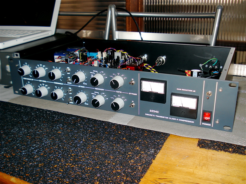
I'm having some really bizarre issue with my comps. The short story is they work and sound fantastic, really really over the top fantastic. Now for the long story...
-My ratio switch is a 12 pos switch, all the front panels I've seen have 5 pos marked, the first 5 positions (from ccw to cw) effect the sound then the remaining positions have no effect. On the schem its a 12 pos switch with only the first 5 pos connected to anything.
-Similar issue with threshold, fully ccw behaves as expected and as the switch is turned behavior is normal, but after the fifth position the unit stops compressing. By using the +10 switch, even with the limited range of the controls, I can get the full range of compression from a few dbs to heavy squishing with a 0dbu (0.777v) signal.
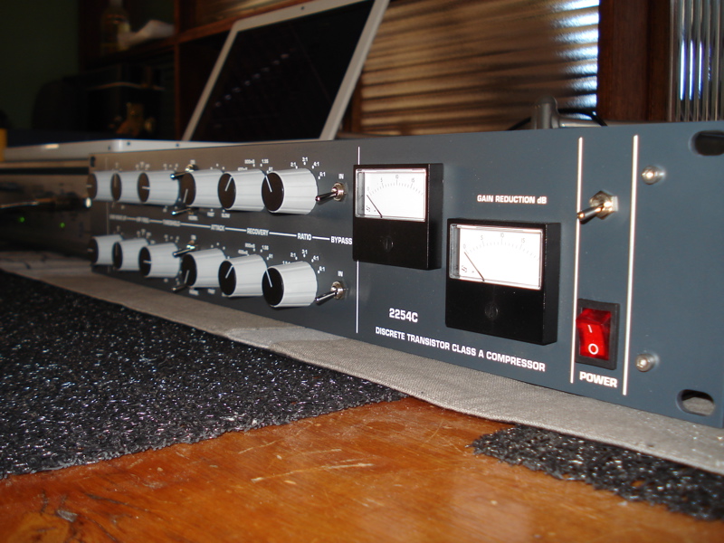
-meters, they don't track exactly the same, in a non uniform way. What I mean is, adjusting the threshold the needles will go from pretty close, to kind of off, then back then the other way. It's always generally ok, but just kind of weird. Also, the scale is very inaccurate, at both of the far ranges (20 & 2) it's pretty right on but in the middle it's off by quite a bit.
-release, on one channel the ccw position causes the compressor to "stick". It's like it doesn't release at all. Also, the wacky-ness of the meters really changes with different release times.
In a way I'm not super concerned since it works, and sounds great but I'd like to see if I can get to the bottom of some of this mumbo jumbo. I screwed up and didn't match the diodes, but the two channels are very closely calibrated. On some settings as little as 2/10th of a db difference and sometimes as much as 7/10ths.
let me know what you think.
-My ratio switch is a 12 pos switch, all the front panels I've seen have 5 pos marked, the first 5 positions (from ccw to cw) effect the sound then the remaining positions have no effect. On the schem its a 12 pos switch with only the first 5 pos connected to anything.
-Similar issue with threshold, fully ccw behaves as expected and as the switch is turned behavior is normal, but after the fifth position the unit stops compressing. By using the +10 switch, even with the limited range of the controls, I can get the full range of compression from a few dbs to heavy squishing with a 0dbu (0.777v) signal.
-meters, they don't track exactly the same, in a non uniform way. What I mean is, adjusting the threshold the needles will go from pretty close, to kind of off, then back then the other way. It's always generally ok, but just kind of weird. Also, the scale is very inaccurate, at both of the far ranges (20 & 2) it's pretty right on but in the middle it's off by quite a bit.
-release, on one channel the ccw position causes the compressor to "stick". It's like it doesn't release at all. Also, the wacky-ness of the meters really changes with different release times.
In a way I'm not super concerned since it works, and sounds great but I'd like to see if I can get to the bottom of some of this mumbo jumbo. I screwed up and didn't match the diodes, but the two channels are very closely calibrated. On some settings as little as 2/10th of a db difference and sometimes as much as 7/10ths.
let me know what you think.


")