You are using an out of date browser. It may not display this or other websites correctly.
You should upgrade or use an alternative browser.
You should upgrade or use an alternative browser.
D-LA2A Support Thread
- Thread starter [silent:arts]
- Start date


Help Support GroupDIY Audio Forum:
This site may earn a commission from merchant affiliate
links, including eBay, Amazon, and others.
yep, I'm going off of that. I just was wondering about High End Mastering build. That BOM is very helpful just checking on a few of the "options".
Also, does anyone have an answer to what are the proper relays to be using? Seems the 653-G5V-2-DC5 are not working properly for some guys and they are also on back order from mouser. Any ideas of a different part that will work fine?
EDIT: How about this one from mouser? G6A-274P-ST40-US-DC5 or Digi Key has the 653-G5V-2-DC5's.
EDIT: How about this one from mouser? G6A-274P-ST40-US-DC5 or Digi Key has the 653-G5V-2-DC5's.
Kingston
Well-known member
Those original 5V Omrons are perfect. They are just about the most trustworthy part on this whole layout. If you can't find them, any other small signal 5VDC relay that has the same layout can be used as a replacement. They are nothing but DPDT switches afterall.
If they are not working it's always a user error. Error in the 5V supply, or possibly diodes soldered the wrong way around. Besides, you don't actually need the diodes in this circuit.
If you are interested in the sound of different caps, see the original LA2A help thread. There was plenty of discussion just some months back. To recap, use cheap/standard electrolytics for LA2A like your grandma used to make or use PIO caps (russians are cheap) for the very high end.
- Joined
- Jul 15, 2009
- Messages
- 2,301
All you have to know about those relay if you read my comments on the first page is that the ideal is to have an unpolarized realy that will work no matter how and you dont have to change the diode, if you do have polarized relay check the polarity the 5V + side will be fed by the right side of the board if looking at the normal position in the chassis, i had the experience with the the substitue relay by mouser had the + side on the left side ( watch the fine prints on the realy it says bottom view so it is actually inverted as you see it), so i did not work at all, you can mount the relay to the bottom of the boards wich will correct the polarity and no change in the diode but not very esthetic or simply make sure that your relay will work whatever the polarity ( unpolarized relay) I also recommend that you mount the relay on a dip socket so if you make a mistake or had the bad relay in there it will be magic to put another one, this pretty covers it, let me know if it works for you
sincerly,
Dany,
sincerly,
Dany,
desol
Well-known member
- Joined
- Jun 20, 2005
- Messages
- 2,126
I am wondering how i can place a switch like Kingston's in place of a 1m pot for the limiter response.
I'd like something switchable rather than variable. The way i understand it is, that at a value of 1m the limiter passes full bandwidth, but with trimmer at fully counter clockwise (no resistance) the limiter doesn't respond to lower frequencies(100hz and down)...is this correct?
So, i'm thinking I would just hang a 1mohm resistor off one side of a spdt switch and nothing off the other side(wire) to get a switchable sidechain effect..
hey guys, i'm getting close!
I plan on ordering this for the main power:
http://www.antekinc.com/cart.php?redirect=http://www.antekinc.com%2Fdetails.php%3Fp%3D671
Does anyone have a suggested 5v transformer for the relays?
Thanks
I plan on ordering this for the main power:
http://www.antekinc.com/cart.php?redirect=http://www.antekinc.com%2Fdetails.php%3Fp%3D671
Does anyone have a suggested 5v transformer for the relays?
Thanks
desol
Well-known member
- Joined
- Jun 20, 2005
- Messages
- 2,126
Well, on my power transformer i have 9v at 1amp on the relay secondary. So, i'd probably say that anything from an-0106 up to an-0109 would be fine. One member took his 5v from the heaters, although i'm not sure how good that would be to do, probably better with a dedicated transformer. Also had a look at your power transformer, as-1t250 looks right rather than the 350. 250 has 4 x outputs and the correct output voltage, whereas 350 only has 2x outputs at a higher voltage.
Desol thanks. That link should be for the AS-1T250. I have it in my cart!
As far as the relays I think I'll grab the An-0005. Seems simple enough.
Let me know if I should be looking someplace else.
The only thing left to get are transformers and Optos from Drip! I can't wait to use this baby.
As far as the relays I think I'll grab the An-0005. Seems simple enough.
Let me know if I should be looking someplace else.
The only thing left to get are transformers and Optos from Drip! I can't wait to use this baby.
The relays on the BOM our out of stock everywhere for months. Does anyone know if this is a good alternative?
http://search.digikey.com/scripts/DkSearch/dksus.dll?Detail&name=19022E2U0-ND
http://search.digikey.com/scripts/DkSearch/dksus.dll?Detail&name=19022E2U0-ND
band_master
Well-known member
- Joined
- Mar 14, 2011
- Messages
- 68
hey guys,
i just finished my build, been reading up a ton on this thread. feels good to make my first post! I fired up the unit last night and have a couple issues...
1. I don't seem too have much gain. I have to set the pot to 7 or 8 to match the level when bypassed. this is for both channels.
2. if i set the gain on channel 2 above 8 the needle is buried and i get distortion.
3. i have to turn the gain and peak red knobs all the way up to meter any GR at all. I assume this is related to low input gain?
I am using Edcor WSM 600/15K input and 15K/600 output and following the wiring below. Is this correct? Pin 2 and Ground are both the center tap, yes?
INPUT edcor XSM 600/10k
edcor pin 1 = 4383 brown
edcor pin 2 = 4383 pink
edcor pin 4 = 4383 green
edcor pin 5 = 4383 blue
edcor pin 8 = 4383 grey
edcor ground= 4383 black
OUTPUT edcor XSM10k/600
edcor pin 1 = 8940 yellow
edcor pin 4 = 8940 green
edcor pin 5 = 8940 grey
edcor pin 8 = 8940 pink
edcor ground= 8940 black
I am wondering if perhaps i damaged the 12BH7A tubes? I had them swapped out with the AX7 in VX03 in both channels. When I first installed the meters I was reading some GR but then I used the Zero adjust RVX04 pots to set them to zero as per the La2a manual.
I also installed a 100K pot at RX27, do I need to ground that or no?
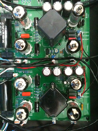
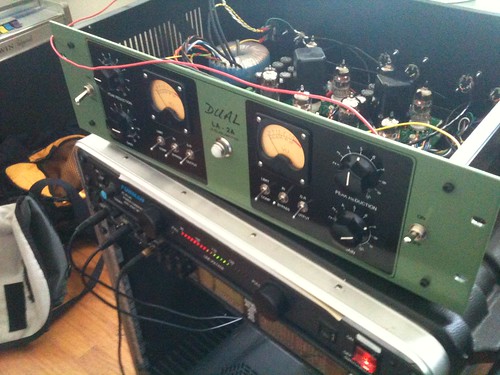
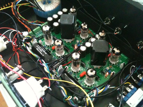
I also tried turning RVX37 and RVX03 all the way counter clockwise. This had no effect. Stereo link mode also seems to not be working, but I figure first thing is to figure out what is wrong in dual mode. here are some pics, the nice faceplate was made by Dan at Collective Cases. Thanks Dan and Thanks Volker for the wonderful PCB!!!
BD
i just finished my build, been reading up a ton on this thread. feels good to make my first post! I fired up the unit last night and have a couple issues...
1. I don't seem too have much gain. I have to set the pot to 7 or 8 to match the level when bypassed. this is for both channels.
2. if i set the gain on channel 2 above 8 the needle is buried and i get distortion.
3. i have to turn the gain and peak red knobs all the way up to meter any GR at all. I assume this is related to low input gain?
I am using Edcor WSM 600/15K input and 15K/600 output and following the wiring below. Is this correct? Pin 2 and Ground are both the center tap, yes?
INPUT edcor XSM 600/10k
edcor pin 1 = 4383 brown
edcor pin 2 = 4383 pink
edcor pin 4 = 4383 green
edcor pin 5 = 4383 blue
edcor pin 8 = 4383 grey
edcor ground= 4383 black
OUTPUT edcor XSM10k/600
edcor pin 1 = 8940 yellow
edcor pin 4 = 8940 green
edcor pin 5 = 8940 grey
edcor pin 8 = 8940 pink
edcor ground= 8940 black
I am wondering if perhaps i damaged the 12BH7A tubes? I had them swapped out with the AX7 in VX03 in both channels. When I first installed the meters I was reading some GR but then I used the Zero adjust RVX04 pots to set them to zero as per the La2a manual.
I also installed a 100K pot at RX27, do I need to ground that or no?
I also tried turning RVX37 and RVX03 all the way counter clockwise. This had no effect. Stereo link mode also seems to not be working, but I figure first thing is to figure out what is wrong in dual mode. here are some pics, the nice faceplate was made by Dan at Collective Cases. Thanks Dan and Thanks Volker for the wonderful PCB!!!
BD
[silent:arts]
Well-known member
Hi BD,
nice your registration to the forum finally did happen")
first, wire your Edcors correct, without any center taps
INPUT edcor XSM 600/10k
edcor pin 1 = 4383 brown
edcor pin 4 = 4383 green
edcor pin 5 = 4383 blue
edcor pin 8 = 4383 grey
ignore pink and black
OUTPUT edcor XSM10k/600
edcor pin 1 = 8940 yellow
edcor pin 4 = 8940 green
edcor pin 5 = 8940 grey
edcor pin 8 = 8940 pink
ignore black
nice your registration to the forum finally did happen
first, wire your Edcors correct, without any center taps
INPUT edcor XSM 600/10k
edcor pin 1 = 4383 brown
edcor pin 4 = 4383 green
edcor pin 5 = 4383 blue
edcor pin 8 = 4383 grey
ignore pink and black
OUTPUT edcor XSM10k/600
edcor pin 1 = 8940 yellow
edcor pin 4 = 8940 green
edcor pin 5 = 8940 grey
edcor pin 8 = 8940 pink
ignore black
Ok, before I solder all these resistors in I want to make sure I am 100%. So according to the BOM for a 100K switch I place the 10.5k resistor at position 0 not position 1 on the ELMA?
Does this mean that position 22 has no resistor?
Does this mean that position 22 has no resistor?
azone said:2. Elma 24-position switches [edited]
I installed the resistors to the Elma switches. Two of them are set for 100k log and two for 33k log (to be used in series with 68K resistor for less gain).
If you haven't used switches like this before where you add your own resistors etc.. it can be confusing.
a) Look at it as a potentiometer, a voltage divider, since this is what it is anyway, a stepped attenuator. Check out this Elma schematic from the Goldpoint Level controls website http://www.goldpt.com/schm_ser.html

b) Realize that the end-stop is before position 0, and the first resistor R1 should go at position 0.
c) The marking on the Elma part shows 0 to 22. These marking fall between switch positions and can be thought of as resistor numbers. There will be (23) resistors total when completely fitted.
d) Use silent:arts log-pot-to-switch excel document to calculate the resistor values.. http://www.silentarts.de/DIY/PM660/LogPotToSwitch.xls


band_master
Well-known member
- Joined
- Mar 14, 2011
- Messages
- 68
thanks volker! just got a chance to fix the i/o xformers last night and now i am getting HUGE gain. also, it seems like the link mode is working properly as well. I will do some more calibration and testing over the weekend. quick question though, what is the best way to wire power to the jeweled power lamp and meter LEDs?
[silent:arts]
Well-known member
first make sure (with a cheap pot) if you really want a 100k switch.dandeurloo said:Ok, before I solder all these resistors in I want to make sure I am 100%. So according to the BOM for a 100K switch ...
at least for "gain" I doubt this.
would be a pain to unsolder all resistors and replace it with new ones ...
[silent:arts]
Well-known member
good news !!!band_master said:thanks volker! just got a chance to fix the i/o xformers last night and now i am getting HUGE gain. also, it seems like the link mode is working properly as well. I will do some more calibration and testing over the weekend. quick question though, what is the best way to wire power to the jeweled power lamp and meter LEDs?
best way to power up meter lamps etc is to use the relay switch PSU
[silent:arts] said:first make sure (with a cheap pot) if you really want a 100k switch.dandeurloo said:Ok, before I solder all these resistors in I want to make sure I am 100%. So according to the BOM for a 100K switch ...
at least for "gain" I doubt this.
would be a pain to unsolder all resistors and replace it with new ones ...
No for the gain I will be using the 25k resistors BOM. The 100K is for the gain reduction. I'm going according to the BOM.
[silent:arts]
Well-known member
fine.
for your question we need to know:
- do we start counting at 0 or 1
- do you want 23 or 24 steps
the picture shown starts counting at 1, and has 24 steps
for your question we need to know:
- do we start counting at 0 or 1
- do you want 23 or 24 steps
the picture shown starts counting at 1, and has 24 steps
Thanks for your guidance here!
I honestly am just wondering what the Azone USA BOM is for. I am fine with 23 or 24 positions. I mainly just want to make sure I have it right according to the parts in the USA BOM.
I currently have them all starting from position one because when I check the switch with a continuity meter in the most left position (volume all the way down) it started at position 1. So I thought I had it right until I read the post from Azone where he said to start from the zero position.
I also have the resistance in the position starting at the highest value (10.5k) for the most resistance which makes sense to me for the most left position.
Maybe now that I think of it, it should start on 0. That way with the attenuator all the way to the right (volume up) then it would be just straight wire. Current I have straight wire at position 0.
Ok, I hope someone can help me make sense of it.
Thanks
[silent:arts]
Well-known member
if we start counting from position 1,
type in (at the LogPotToSwitch Excell file)
Lowest Switch Nr is: 1
type in
Desired Impedance: 25000 (for 25k)
type in your switch positions:
23 or 24
connect "GND" to switch position 1
connect resistor 1 from pin one to two
repeat ...
for a 23 position switch you will end at position 23, connect pin 23 to "In"
(no resistor between position 23 and 24, no connection to position 24)
for a 24 position switch you will end at position 24, connect pin 24 to "In"
hope this helps