D-LA2A Support Thread

GroupDIY Audio Forum

Help Support GroupDIY Audio Forum:

This site may earn a commission from merchant affiliate links, including eBay, Amazon, and others.
@frazzman

Did you reflow the tube socket joints and the molex connector joints under the PCB? you should definitely use shielded wire for the limit/comp switch. moving that wire around and even touching the switch i have found it is noisy even with a shielded pair. have you tried replacing the female molex connector for the limit/comp switch?
 
Hi guys,

The problem is still there irrespective of the limit / comp switch plugged in. The problem is present with none of the switches or pots connected.
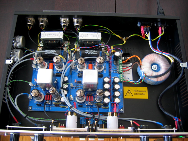
As I mentioned, the working channel can pass clean audio with all switches and pots disconnected. That is not the case on the left side. No matter what, the issue is present until I press my thumb firmly against the PCB. I am thinking it has to be the heater wiring ...  I did reflow solder on all molex connectors
 
you might have a broken PCB trace. long shot but I had a hum problem with an access 312 build and it turned out that the solder pad had lifted and become broken inside of the solder joint.
 
Btw.: All NRG Recording forum links in the OP are broken as it has moved to http://www.energyrecording.de (previously http://www.nrgrecording.de/nrg). So e.g. the link for the ground scheme is now:
http://www.energyrecording.de/viewtopic.php?t=405&postdays=0&postorder=asc&start=3
 
salomonander said:
ps: if i may make a modest suggestion for the next revision of the board...
it would be amazing if the signal would travel to the t4b in bypass mode. switching out is great and clean. but whenever switching back into compression mode one gets a dynamic spike (a big one when doing lots of reduction) since the t4b has to catch up first...
A few solder bridges and you are done:
 

Attachments

  • Bildschirmfoto 2014-06-09 um 13.29.23.png
    Bildschirmfoto 2014-06-09 um 13.29.23.png
    137.7 KB · Views: 84
Thanks for everyone's help... I stripped the heater wiring on my dodgy left channel and cleaned it all up and did it fresh and cleanly and problem is gone ... I suspect the wiring to the top left tube socket had a become a dry joint - then when I pressed on the PCB around that area the problem would go. Everything is back to normal now on both channels .. I could swear my working channel passes audio with no switches or pots connected... I could be wrong
 
[silent:arts] said:
salomonander said:
ps: if i may make a modest suggestion for the next revision of the board...
it would be amazing if the signal would travel to the t4b in bypass mode. switching out is great and clean. but whenever switching back into compression mode one gets a dynamic spike (a big one when doing lots of reduction) since the t4b has to catch up first...
A few solder bridges and you are done:

great thanks!
 
ok so i sorted everything out. the meters not showing the right amount of compression was simply a wrong value trim pot in the R3 postition (somehow installed 100Ohms instead of 100k :)

there is still one problem though. my 5v regulator ic gets way too hot. i do have a heatsink installed. when touching it one can get a serious burn. plus my vu lights shut down after a while when it gets too hot (we had over 34 degree today - no problems last night). restarting the unit solves this.
im wondering if my heatsink is too low budged (it was some cheap one from an electric store around the corner) or if my lamps are the problem. i do have 6,3v 1,6W 0,25A lamps installed in my meters. not leds. i dont even know if there are "good" or "bad" heatsinks - so any help would be great. i want to close the lid on this and move on :)
 
salomonander said:
ok so i sorted everything out. the meters not showing the right amount of compression was simply a wrong value trim pot in the R3 postition (somehow installed 100Ohms instead of 100k :)

there is still one problem though. my 5v regulator ic gets way too hot. i do have a heatsink installed. when touching it one can get a serious burn. plus my vu lights shut down after a while when it gets too hot (we had over 34 degree today - no problems last night). restarting the unit solves this.
im wondering if my heatsink is too low budged (it was some cheap one from an electric store around the corner) or if my lamps are the problem. i do have 6,3v 1,6W 0,25A lamps installed in my meters. not leds. i dont even know if there are "good" or "bad" heatsinks - so any help would be great. i want to close the lid on this and move on :
Your regulator is going into thermal shutdown from overheating! You need to install a bigger heatsink, bigger the better... Get some thermal paste too. Should be an easy fix
 
connect it to the chassis (isolated). or use a better performing heatsink.

with the weather in germany today we have one further problem:
too much power, resulting in higher voltage, a result of our Energiewende (solar is working).
at the moment you even get money for waisting electrical power.
we are already selling to our EU neighbors with negative prices.

http://www.welt.de/wirtschaft/energie/article128800398/Extreme-Belastungsprobe-fuer-deutsches-Stromnetz.html
 
frazzman said:
Thanks for everyone's help... I stripped the heater wiring on my dodgy left channel and cleaned it all up and did it fresh and cleanly and problem is gone ... I suspect the wiring to the top left tube socket had a become a dry joint - then when I pressed on the PCB around that area the problem would go. Everything is back to normal now on both channels ..

8) Great you sorted this out!

frazzman said:
I could swear my working channel passes audio with no switches or pots connected... I could be wrong

well, it even passes audio without power ;-)
without the "IN" switch connected (often misread as "bypass") the relays are in bypass mode.
look at the schematic, without the gain pot there can't be any signal.
 
[silent:arts] said:
frazzman said:
Thanks for everyone's help... I stripped the heater wiring on my dodgy left channel and cleaned it all up and did it fresh and cleanly and problem is gone ... I suspect the wiring to the top left tube socket had a become a dry joint - then when I pressed on the PCB around that area the problem would go. Everything is back to normal now on both channels ..

8) Great you sorted this out!

frazzman said:
I could swear my working channel passes audio with no switches or pots connected... I could be wrong

well, it even passes audio without power ;-)
without the "IN" switch connected (often misread as "bypass") the relays are in bypass mode.
look at the schematic, without the gain pot there can't be any signal.

Hey Volker - sorry of course you are right...! I should have said everything disconnected except for "IN" switches otherwise as you said it would be in bypass mode. But looking at the schem I can see what you mean about the gain pot. I know for sure audio passes without limit / comp switch connected. Not though I can even hear the difference with this switch (... True to the original ...) Geez who knows, I'm delirious after fixing this bad boy. Just glad it's working :) thank you for your help and all other members!
 
[silent:arts] said:
connect it to the chassis (isolated). or use a better performing heatsink.

with the weather in germany today we have one further problem:
too much power, resulting in higher voltage, a result of our Energiewende (solar is working).
at the moment you even get money for waisting electrical power.
we are already selling to our EU neighbors with negative prices.

http://www.welt.de/wirtschaft/energie/article128800398/Extreme-Belastungsprobe-fuer-deutsches-Stromnetz.html

hey Volker

thanks. so basically connect a cable from the heatsink to starground? am i understanding this right?
 
[silent:arts] said:
with the weather in germany today we have one further problem:
too much power, resulting in higher voltage, a result of our Energiewende (solar is working).
at the moment you even get money for waisting electrical power.
we are already selling to our EU neighbors with negative prices.

http://www.welt.de/wirtschaft/energie/article128800398/Extreme-Belastungsprobe-fuer-deutsches-Stromnetz.html

  sorry to get off topic , but is there a way I can convert/ translate that article in to English ??  would love to read it and hear about all the great clean energy the rest of the world is doing :)
 
[silent:arts] said:
salomonander said:
thanks. so basically connect a cable from the heatsink to starground? am i understanding this right?
no. mount the regulator + heatsink isolated to chassis.
chassis will be a further heatsink.


got it thanks. by isolated you mean detached from the pcb right? so simply drill an m3 hole and put the regulator plus heatsink there via three wires? sorry for new noob questions.... i am a noob :)
 
salomonander said:
by isolated you mean detached from the pcb right? so simply drill an m3 hole and put the regulator plus heatsink there via three wires?
by isolated i mean electrical isolated:
http://www.aosmd.com/res/application_notes/package/AN101_TO220_Guidelines.pdf

wires are fine, or just solder to the bottom like I did:
IMG_3981.jpg
 
the plastic washer between regulator and heatsink is VERY important!!! If you look closer you will see that the metal screw is also isolated from the heatsink (ground).

IMG_20131223_193224_721.jpg


regards
Bernd
 

Latest posts

Back
Top