college101
Well-known member
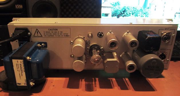
Looks good!!!


college101 said:Ok guys...last attempt to get this right has failed again..I get signal in +4 and nothing happens in GR mode
I found a Capacitor I had that wrong value in, and swapped it out...still no change...Ive lost a lot of hope that this project is even do-able
Can you guide me again, to get back on track?
college101 said:Explain the ghetto night light version test Kazper...I probably need to do it~!
My unit does pass audio...it just does not work in GR mode
I will be taking new measurements soon...
The LA2A should pass audio in all modes and compress when the front left (=gain reduction) knob is turned clockwise.
(And if enough signal is present on the input)
college101 said:I am at work today, and then college tonight...Having a baby with the wife tommorow...I wont get time to check voltage points till friday or saturday, once the new baby is sleeping!
I dont hear compressed audio when I trun peak reduction( I thought this would be affected by turning the pots on the back of the unit, I adjust those two pots and still no difference...
The needle jumps to zero when I select the GR mode,then if I have my cd player playing into my new yamaha mixer, into the 2A, the needle does not move...its like it is not even registering that signal is going through it... but the audio is playing out my guitar amp!
most of the people on here are real DIY types...they make their own cases...get creative and unique

Enter your email address to join:

