API 325 to 312 Convert! A New Thread.

GroupDIY Audio Forum

Help Support GroupDIY Audio Forum:

This site may earn a commission from merchant affiliate links, including eBay, Amazon, and others.

Marc Girard

Well-known member
Joined
May 15, 2005
Messages
113
Location
Montreal, Canada
Hello all,

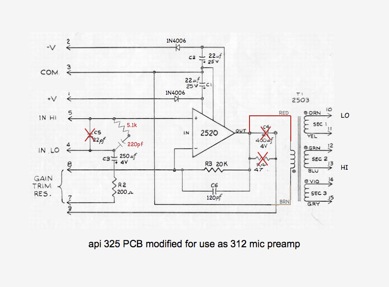
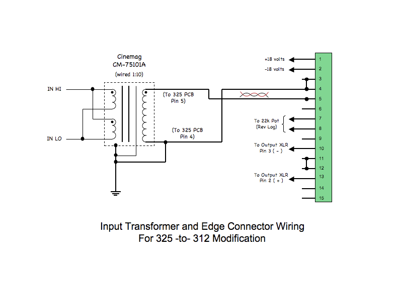
I just got 2 real nice API 325 cards from a friend.  They're 100% original and I'd like to convert them to 312s.  I've searched the threads and the net extensively but haven't found all the correct info.

For what I understand, I need to buy and install Input transformers (a AP2622 clone).  I'm thinking about the Cinemag CMMI-8-PCA as their made by the original guys (well, OK, the son of the original guy!).  Since they're original 325 boards (not the blue ones, they're green with 2 big orange capacitors).  I'd like to stay close to the vintage API sound.  I've read about Sowter's 9820s too, but they look expensive.

Now, there's some mods to be done on the card itself.  I'm not an expert at decoding schematics.  Is there a simple list, some sort of "To-Do" listed somewhere?  The closest I've got is a part list from Digikey.  I've looked on the net (found a few links on the metas) but they're all dead.

I plan to use JLM Audio's excellent PSU kit and GoBetween switches to keep things simple. 

Thanks for any info and sorry if this has been covered in the past, might be good to refresh the subject! :)

Marc Girard
www.bluaudio.org
www.marcgirard.com
 
api325mods.jpg


I think this is from Peter Purpose??
 
It's pretty easy Marc. Just takes a bit of time and effort to figure it out.
I did six of these and so far they've turned out great. Don't use the parts list
in the thread, as there are some SMD parts in there that shouldn't be.

As a start, all the numbers on the left side of the schematic going down with the arrows
are the pin contacts on the edge connector of the card. Follow the numbers and you should
see the parts on your card. Pin 1, pin2, pin3...etc.

Then follow Peter's suggestions on replacements. I ordered all my stuff from digikey.

D.
 
Really theres nothing tricky in any API preamp or line card.
First learn how does it works and learn to read a schematic bro.
then all things to change will become obvious.
I dout you have more than half an hour work to do...

002 cents.
 
Marc Girard said:
Thanks for posting that quickly but please read my post carefully, I said: I'm not a pro, not very good at decoding schematics! :(

MG

Nor am I.  But you've only got a small handful of components on that board.  The caps are labeled well enough to figure out what's what.  Anything pf is more than likely a ceramic disc and anything with a "+" and a voltage is going to be an electrolytic.  You've got 2 diodes to swap and 2 resistors to find.  Plus, the original values are still on the schematic for comparison.  Just spend some time looking at what you've got and where it is in the original schematic and swap away. 
 
I got a bunch of 325's that I converted to 312's at my studio.  Documented it, but never got around to sharing it with the group, so here it is:

312 schematic:
312drawing.png


325 schematic:
325drawing.png


325 pcb circuit changed for use as a 312:
325wired_for312.png

Be aware the the 5k1/220pF zobel is for the specified 2622 input transformer.  Make sure to use the zobel recommended for the input transformer you use. 

Next, you'll notice the 1000pF caps from the 312 drawing are gone.  These are not needed on most input transformers (were used originally with 2622 inputs), and even if you do decide to use them they'd be at the input transformers, not on the 325 pcb.

Also the "X's" indicate parts that are removed altogether.  DO NOT jumper these components with a wire instead, just remove them.


And the input transformer and edge connector wiring (I used Cinemag's 75101 on mine -- loverly):
325_as_312_trafo__connector.png


Just study the drawings and go slow.  You'll love the result.  A beautiful preamp if there ever was one!

Much peace,

JC


things can change a bit if you use a 10k pot, here's a little more info-http://www.groupdiy.com/index.php?topic=26948.0

Arty
 
RascalSeven, YOU'RE THE MAN!  Thanks a lot!  This is what I was looking for, a "325 to 312 for Dummies" type of thing! :)  Now, is there a big difference between a Cinemag CM-75101A and a CMMI-8-PCA?  Your 75101 is labeled as "vintage" on Cinemag's web site (I must admit, I kinda like this! hehehe).  Thanks for letting me know!    Could you also post the 1:10 wiring diagram for the xformer?  That'd be awesome, thanks again!
 
I was looking at the schematics trying to slowly decode all the info.  I noticed that my 325 cards might be a little different.  I've got different values on the caps.  Here's close up shots for you guys to see what I'm talking about.

API325-Front.jpg


API325-Back.jpg


At first, I thought my 325 boards might have been modified.  After looking around the net for more info, I found a PDF of the original API documentation with a photo my 325s.  So, they might have done several versions of the 325s.  Anyway, let me know if there's some gotchas around, thanks in advance!
 
rascalseven said:
Next, you'll notice the 1000pF caps from the 312 drawing are gone.  These are not needed on most input transformers (were used originally with 2622 inputs), and even if you do decide to use them they'd be at the input transformers, not on the 325 pcb.

Also the "X's" indicate parts that are removed altogether.  DO NOT jumper these components with a wire instead, just remove them.


JC,

Does it matter if the primary on the 2503 is reverse connected? Pin 9 goes nowhere...
I wouldn't think so...but..

What are the 1000pf cap's on the 2622 for? I've never been able to find this out?

D.

EDIT: Searched and found answers!
 
Sorry for the delay.  I've been trying to catch up with my business.

Marc Girard said:
Could you also post the 1:10 wiring diagram for the xformer?  That'd be awesome, thanks again!

That actually is the 1:10 shown (that's what I used).  You can check out that and 1:5 connections at http://cinemag.biz/mic_input/cm-75101APC-schematic.html

Marc Girard said:
I was looking at the schematics trying to slowly decode all the info.  I noticed that my 325 cards might be a little different.  I've got different values on the caps..........  At first, I thought my 325 boards might have been modified.  After looking around the net for more info, I found a PDF of the original API documentation with a photo my 325s.  So, they might have done several versions of the 325s.  Anyway, let me know if there's some gotchas around, thanks in advance!

Your card looks correct to me.  This conversion will require you to pretty much gut that card and put new components (different values) in.  The 470u/6.3v you have along the top of the picture is an appropriate replacement for the 400u/4v originally specified.  When companies (or service techs) make substitutions for original values, they generally use a the same or slightly higher values (hence the 400u becoming 470u and the 4v becoming 6.3v).  Not a big deal, so don't get hung up on that.

FWIW I used a jumper in place of that cap on some of my 325 cards (in spite of my directions above).  On the card layout that cap connects the opamp's output to the pad where the 2503 primary is.  On some of my cards there was enough red wire to reach the opamp output without the jumper, but several had the red lead cut too short, so a jumper was necessary.  Hope that helps.

desol said:
Does it matter if the primary on the 2503 is reverse connected? Pin 9 goes nowhere...
I wouldn't think so...but..

What are the 1000pf cap's on the 2622 for? I've never been able to find this out?

D.

EDIT: Searched and found answers!

Glad you found answers.  FWIW, I believe the 1000pF's were to help stabilized the circuit.  And if you don't swap the primaries (brown and red leads on the 2503) your signal's polarity will be inverted relative to a 312 circuit.

dude24man said:
what happens to C3 and R2 in the convertion process. Arty

I change them to the values of C3 and R2 from the 312 drawing (that is, 250uF and 200R, respectively).

JC
 
3nity said:
JC if you look really close theres a diode different than the other...

Ah, yes, I see that now.  That's been done since leaving the factory.  Definitely not stock like that.  Replacing both with new 1N400x as specified on the conversion schematic will do nicely.

JC
 
Thanks for the reply JC. Very cool...

We could also take things one tiny step further and then this thing pretty much is
identical to the 312, without any cut traces. 200 ohm resistor(r2) simply goes on the
edge connector.


I did the cap upgrades that Peter Purpose suggested. The 220 uf's on power rails...
and the 1000uf on the pot...i used 680uf here. This is one card completely modified over.
The other cards have r2 in place normally. May change em all over...don't know yet.
They all sound amazing tho...


2622's strapped in with JLM's(will probably add 1000pf's):
Notice the actual...'rails'.  :)


desol said:
Thanks for the reply JC. Very cool...

We could also take things one tiny step further and then this thing pretty much is
identical to the 312, without any cut traces. 2oo ohm resistor(r2) simply goes on the
edge connector.

I'm not sure I understand the comment.  I didn't cut any traces on my pcb's.  Cuts aren't required for the mod I describe above.  The new 200R resistor goes in the spot where the 470R (R2) previously was.  The pot is connected to pins 7 and 8 on the edge connector.  Yes, you could put a jumper in and then hang the 200R on the edge connector, but why add two components when swapping with one is all that is needed?

Or maybe I'm misunderstanding?  I apologize if that is so.

JC
 

Latest posts

Back
Top