You are using an out of date browser. It may not display this or other websites correctly.
You should upgrade or use an alternative browser.
You should upgrade or use an alternative browser.
Barry Porter "Net EQ"
- Thread starter guitarmaker
- Start date
Help Support GroupDIY Audio Forum:
This site may earn a commission from merchant affiliate
links, including eBay, Amazon, and others.
Harpo
Well-known member
Yepp. The loading on the filter driving stage (U2-A) is still the same. For adding more filter bands for whatever reason, some unity gain buffers in front of the filter inputs might be needed.
Harpo
Well-known member
Instead of FI relay K3, switching between the peaking and shelfing low band, you have an additional center tapped pot or rotary switch substitution in parallel to the other level pots with wiper connecting thru a 2K2 to the decoupled filter output (junction C45/R50). Leave out K3,D3,Q3,C37,R34,R36,R103,S2,LED2 and jumper K3-pin2 with pin3 at pcb.prescott said:But how can I adjust the volume of the shelv and peak to differect positions at the same time?
Where can I connect another rotary to?
Same for the high peak/shelf band with corresponding parts.
Consider you might run out of frontpanel real estate at some point or fingers are not small enough to comfortably fit between knobs ...
petermontg
Well-known member
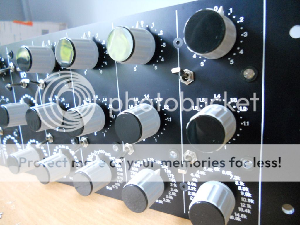
My knobs arrived.......


skidmorebay
Well-known member
- Joined
- Aug 1, 2011
- Messages
- 134
Hi,
Anyone care to share how much they spent to finish this project?
thanks,
JS
Anyone care to share how much they spent to finish this project?
thanks,
JS
petermontg
Well-known member
Anywhere, from 1-2.5k, depending what rotary switches you choose and of course less man hours.....
skidmorebay
Well-known member
- Joined
- Aug 1, 2011
- Messages
- 134
Thanks!
Harpo, or anybody, could you post a new link to the spreadsheet of resistor values? When I click on the link labeled "Hop" in the earlier posts I just get a screen full of random characters....
JS
Harpo, or anybody, could you post a new link to the spreadsheet of resistor values? When I click on the link labeled "Hop" in the earlier posts I just get a screen full of random characters....
JS
Harpo
Well-known member
JS, no link broken. Maybe use right-click / save_as for a workaround (some program might have occupied the standard file extension .XLS for a different -no more related to MS-Excel or OpenOffice calc sheet- purpose).
druu
Well-known member
petermontg
Well-known member
I have a small problem with mine.
The 10r in R18 which is on the -18v line keeps blowing out, have checked my PS and everything is fine there.
Any ideas?
The 10r in R18 which is on the -18v line keeps blowing out, have checked my PS and everything is fine there.
Any ideas?
petermontg
Well-known member
Thanks Paul.
Checked the following Cap with the MM and it's polarity is labelled wrong.
Must of been an ebay purchase I will check it later tonight.
Edit: Some bad ceramics....
Checked the following Cap with the MM and it's polarity is labelled wrong.
Must of been an ebay purchase I will check it later tonight.
Edit: Some bad ceramics....
MrBlomski
Well-known member
druu said:Another complete! Just need to go through the calibration but so far it all checks out fine.


Huge thanks to Harpo, ppa and the usual guys I hassle over PM.
For anyone thinking to add +/-6dB Input Gain control, see here. Works perfectly (Thanks ppa)
Do I see a DR-MQ5 eq?
druu
Well-known member
No, that EQ below the BP is built using Igor's GML/Massenburg 'MEP250' boards with MS/Bypass, before the DR-MQ5 copies came out. 
1.The PCB has a 6 pin footprint for the switches, and the schematic has a DPDT switch drawn up for the bypass switches, but is there any reason why I couldn't just use a single pole on/off switch and tap into the two "relevant" points on the board for each of the four switches?
2. Frame = chassis on the 10 pin connector?
If you are using Harpo's excellent excel sheets, this should be a correct list of the resistor changes on the board.
Cut (freq)
R114, R115
R111 R112
R108 R109
R105 R106
Short (freq)
R87 R61
R83 R58
R79 R55
R74 R51
Short (shelving)
R78
R91
Replace values (Q)
R99 R100 R101 R102 = 10K
R95 R96 R97 R98 = 5K1
Short (Q)
R104 R107 R110 R113
Replace values (Gain)
R13 R14 = 5K1
R77 R82 R86 R90 = 6K49
Short (HPF)
R93 R 94
Attachments
druu
Well-known member
Single pole is all that's required. The extra pole would be there to add rigidity if mounted to the board.
petermontg
Well-known member
You can place the last resistor on the chain into the short positions save having them hanging off the rotary.
Similar threads
- Replies
- 0
- Views
- 208
- Replies
- 10
- Views
- 460


