[BUILD] CAPI VP2X~500 Series~Preamp Kit~Official Support Thread

GroupDIY Audio Forum

Help Support GroupDIY Audio Forum:

This site may earn a commission from merchant affiliate links, including eBay, Amazon, and others.
Your t-pad looks to be wired correctly. I would double check the lead colors on the output transformer to make sure they are right.

You don't need to remove the pushbutton switches. Just reheat the solder/pin area until the solder becomes molten again. You can add just a dab of fresh solder if need be. Try to only heat a minimum of time.

There is an in between with the opamps. The problems can be coming from there. It is definitely best to have a known good working amp to check your preamp build with. Once you know you are set there, then you can try an opamp build. Right now, you may have too many variables to really diagnose what is going wrong. Maybe a friend who is close can loan you one?

I also like to limit the attempts to fix things to one thing at a time. If you do more than that, you will never know what the exact problem was.

Cheers, Jeff
 
I FINALLY got round to powering up my first VP26 build ( which is also my first EVER DIY preamplifier build.... ).

It went without a hitch.  Powered up perfectly and sounds absolutely and utterly amazing.

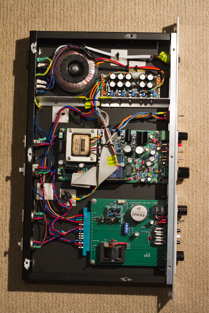
Here are some photos:

http://www.evolutionarytheory.com/2011/09/classicapi-vp26-built-and-tested/

Thanks Jeff!  It was such a pleasurable build for someone reintroducing themselves to DIY after a break of many many years.
 
I just got around to building mine as well - the sound is great, I'm getting a bit more noise when driving a dynamic mic than I'd expect but I haven't started trying to diagnose where that's coming from yet. The only real problems I had were with the millmax sockets (the opamp isn't held super firmly by the sockets, has a tendency to jump out), but most significantly in fitting the newer t-pad output attenuator.

Next to the shaft of the pot there is a small metal clip to help secure the pot to the faceplate and prevent the entire pot assembly from being able to freely rotate. But with the tpad board installed (in what I think is the correct orientation), the tpad circuit board gets in the way of that support clip. I hacked a solution since I had a recording to do tonight - bending the support clip under and just having the pot being free floating. I thought I might have gotten the mini circuit board orientation wrong, but the pot does do what I'd expect, so I'm a bit stumped. I might be able to get pictures up tomorrow, but any ideas based on my description?

Thanks for a great preamp, looking forward to making several more!
 
first off, big thanks to Jeff for making such a superbly fantastic product. This thing has been a dream to work on(regardless of if I did it 100% correctly). Also, thanks to the amazing members of this forum for helping us all out...

this posting is slightly premature as a full report but I've finished my build finally tonight!! and had a few questions/concerns off the bat. I will be able to really test it in my studio tomorrow, tonight I just threw it in a lunchbox and tested it on my laptop mobile rig.

1- when testing my resistance values were odd(at least I think they were).
for example: the -V and v+ read 8.32 M but the value was constantly climbing.  -V and C 1.6M and climbing, +V & C 11 M not climbing, C and O 6.83 M and climbing, +V and O 17.6 M and climbing, and -V and O .77 m and climbing.
this concerned me because I'm new to this and it didn't seem to be correct. I've done continuity tests and also measured resisters before but perhaps I'm doing something wrong with my DMM?

2-When i did finally throw it in the lunchbox and do a super quick test I was very pleasantly surprised that it worked, there was no immediate harsh noise or problems and it seemed to function correctly EXCEPT for that it seems like the PHASE switch somehow got reversed. If i leave the switch out it sounds like I have a high pass filter on at like 10k, it gets super thin and sounds super tinny. If i reverse the phase by engaging it then it sounds wonderful, just like I'm assuming it should sound.  I will follow up tomorrow with a more complete and controlled test in my studio where I know which gear sounds exactly like what but i guess I'm just wondering what I could have done wrong...

Lastly, what is the typical breakup point of this pre Jef? I know my neves like the back of my hand but I want to make sure I didn't screw it up and that it works the way it should, I found that it sounded pretty damn amazing even with a shure sm58 tonight and didn't get too nasty until well past 12 o clock.

Here are some pictures in the meantime if you spot something and say "you idiot!! you reversed the thingamajabber" or whatever.
Thanks SO much


I've picked up the gar so I can build that and see how the sound changes with the different opamps, that'll be next project.
 
oudplayer said:
I just got around to building mine as well - the sound is great, I'm getting a bit more noise when driving a dynamic mic than I'd expect but I haven't started trying to diagnose where that's coming from yet. The only real problems I had were with the millmax sockets (the opamp isn't held super firmly by the sockets, has a tendency to jump out), but most significantly in fitting the newer t-pad output attenuator.
Sounds like your opamp is not fully seated in the sockets. Take a look here for some tips on that. http://classicapi.com/catalog/DOA_Install.php

A few pics of the t-pad area would help. If you have the smaller 388 t-pad, I just bend the tab over or cut it off. The small adapter PCB is designed to be about .05" away from the back of the L-bracket so something may need to be changed here.
 
bigevil said:
1- when testing my resistance values were odd(at least I think they were).
for example: the -V and v+ read 8.32 M but the value was constantly climbing.  -V and C 1.6M and climbing, +V & C 11 M not climbing, C and O 6.83 M and climbing, +V and O 17.6 M and climbing, and -V and O .77 m and climbing.
this concerned me because I'm new to this and it didn't seem to be correct. I've done continuity tests and also measured resisters before but perhaps I'm doing something wrong with my DMM?

2-When i did finally throw it in the lunchbox and do a super quick test I was very pleasantly surprised that it worked, there was no immediate harsh noise or problems and it seemed to function correctly EXCEPT for that it seems like the PHASE switch somehow got reversed. If i leave the switch out it sounds like I have a high pass filter on at like 10k, it gets super thin and sounds super tinny. If i reverse the phase by engaging it then it sounds wonderful, just like I'm assuming it should sound.  I will follow up tomorrow with a more complete and controlled test in my studio where I know which gear sounds exactly like what but i guess I'm just wondering what I could have done wrong...

That was my initial test done very quickly on my laptop and a Apogee One interface. Today I had a chance to really dig into it in my full studio that I know in and out and unfortunately it seems I certainly have a way to go on my soldering and building..... The signal is very quiet and super thin when compared to my other preamps. It sounds like there is a hipass on it at all times, although the mute, and pad switches seem to work, the polarity seems to add some low end back when depressed. The output fader is capable of cutting the output but it doesn't seem to mute it completely when rolled all the way back(perhaps this is as designed). The gain on the preamp also seems to function except that I have to have the gain very far up to even get a useable signal at which point it is very distorted yet still super thin sounding.

I posted pics above ( http://www.groupdiy.com/index.php?topic=33501.msg572952#msg572952 ), will take off the L bracket and post more detailed pics, let me know any thoughts you may have. Thank you so much
 
It looks as though most of the lead colors for the 2503 go to incorrect holes. From what I can see, Brown is the only one that is right?
 
Yea, I meant to solder them in the way they're in now. I must have gotten confused because in the pictures in the manual the colors were different so I substituted based on the order of them coming out of the transformer. This must have been a stupid mistake on my behalf. What would be the proper way? I'm assuming now just to put yellow in yellow, orange in orange. etc....


Yes, yellow to yellow, red to red and so on. Sometimes the order that the leads come out is reversed but the colors always mean the same thing.
 
Wow I'm an idiot. I thought I was being so clever since the order was different. I hope I didn't cut em too short! I guess we'll find out in an hour or so. :) will report back asap. Thanks for the help Jeff

p.s crazy question but when disassembling, do I remove the push button knobs? I don't want to break anything by trying to pull em off.
 
The switch caps are fine to leave on. You may have to splice some of those leads to make them long enough. Just shrink wrap your splices to insure no shorts. Not the most optimum way but worst things have happened. Use the same color leads from the trash if the garbage man hasn't came yet.  ;)
 
Ok, this weekends update.
Luckily I was able to salvage the transformer I'd botched before and get all the wires through the correct corresponding color holes(see new pics). I did the best desoldering/cleaning and re soldering that I could and after finishing securing it back in place I was ready to test using my DMM. unfortunately to my disappointment my readings were once again strange again. At first I was stoked because I did see 200k Ohms resistance which began climbing but then changed to 6.3M. My readings were as follows:
[size=10pt]-V & +V: 6.3M and increasing
-V &  C: 6.12M and increasing
+V & C 20k and then changed to 1.1M and rising
C & O .85 M and increasing
+V & O .57M and increasing
-V & O 1.01M and increasing
[/size]

luckily or unluckily I stripped one of my screws removing the L bracket so until the new L bracket arrives I've got nothing but time to troubleshoot! I'm going to attach pics of where it is at present and maybe someone will be able to point out some other places I could start. Also, are there other tests I could perform using my DMM to find the problem area?

Thanks so much for the help!
Jeff & all you guys rock


A lot of times, the strange really high readings are DMM related. If they were all closer to zero I would be worried. Did you try it yet? I would try firing it up. Your soldering work looks solid so it should work.
 
awesome,
I'll throw it together soon as I get the screws and we'll see!! I'll keep my fingers crossed.

In the meantime would it be a good or bad idea to use a small piece of double sided tape on the tPad (as done with the input transformer)? I used clamps the first time but since i had to disassemble/ rework it I noticed it could be a helpful thing.
 
I just finished 1u racking a VP26 and a Sound Skulptor MP73 and I've blogged about it.  You can check it out here:

http://www.evolutionarytheory.com/2011/09/classicapi-vp26-and-sound-skulptor-mp73-preamps-are-finished/

They both sound AMAZING, it's incredible being able to mix and blend between both sounds.

MG_4660.jpg
 
so, after re soldering my transformer leads and re-assembling the VP25 tonight I finally got it plugged it in and gave it a quick test. all I can say is WOW. I swapped it directly in my normal chain instead of the 1073 and hands down everyone in the room preferred it on my vocal. WHAT a fantastic DIY and incredibly piece of gear. Thanks so much Jeff!
i'm actually nervous I did something wrong cause it sounds so damn good...... couldn't be ACTUALLY working could it????


I'm gonna really dig in tomorrow and give it a full workout on acoustics, bass, more vocals(different mics) and some other fun..... will report back!

In the meantime here she is in her final resting place!
 
jsteiger said:
Your t-pad looks to be wired correctly. I would double check the lead colors on the output transformer to make sure they are right.

You don't need to remove the pushbutton switches. Just reheat the solder/pin area until the solder becomes molten again. You can add just a dab of fresh solder if need be. Try to only heat a minimum of time.

There is an in between with the opamps. The problems can be coming from there. It is definitely best to have a known good working amp to check your preamp build with. Once you know you are set there, then you can try an opamp build. Right now, you may have too many variables to really diagnose what is going wrong. Maybe a friend who is close can loan you one?

I also like to limit the attempts to fix things to one thing at a time. If you do more than that, you will never know what the exact problem was.

Cheers, Jeff

Hey all -

I finally got a pair of functional SL Red Dots to assist in my vp25 build. I also went through and touched up the push button pin/solder joints. Upon testing it out in the lunchbox - I still have all of the same problems..
Here they are again:

-Signal is thin - sound like a very extreme HPF
-Phase switch cuts signal
-Output attenuator is working backwards ( though we confirmed the wiring is correct.. )

I also checked the output transformer wiring (thought i had it right) but after reading some recent posts, I realized that i had wrongly wired the GREY and VIOLET leads coming off the output transformer. I had them going into the 2 holes closest to the transformer ... not the holes that were a label "GREY" and "VIOLET" - Thought I was clever - turned out not!

So, I fixed that mistake and then plugged it back into my lunchbox - and I still have the exact same problems.

Did I damage the output transformer?

I had questionable reads between the 'C' and 'O' sockets when I first built the unit.. now that i've got the Red Dot DOA in it .. i see that the DOA isn't utilizing the 'C' socket..


Thanks for the help so far Jeff - though i've gotten shut down over and over on this maiden voyage - I'm still when sit down and work on.

Thoughts?

Thanks
Max

PS - I've tried multiple mikes, cables, inputs and slots on the lunchbox. Also verified the mics or cable on othe rworking pres.
 
Max,

I would like you to measure all 4 of the 2503's windings. You will be checking the DC resistance. Unfortunately, you will have to desolder all of the leads from the PCB to do this.

Once desoldered, measure:
1. red to brown
2. orange to yellow
3. green to blue
4. violet to gray

Each of these should give you around 8.5 ohms.

Let me know what you find.

Best, Jeff
 
jsteiger said:
Max,

I would like you to measure all 4 of the 2503's windings. You will be checking the DC resistance. Unfortunately, you will have to desolder all of the leads from the PCB to do this.

Once desoldered, measure:
1. red to brown
2. orange to yellow
3. green to blue
4. violet to gray

Each of these should give you around 8.5 ohms.

Let me know what you find.

Best, Jeff

Hey there!

I desoldered and measured the DC resistance between all 4 of the windings.

Here are are the reads: (approximately)

Red to Brown - 8.8 ohms
Orange to Yellow - 8.8 to 9.8 ohms
Green to Blue - 9 ohms
Violet to Grey - 8.8 ohms

I'm guessing that since the reads are closed to 8.5 Ohms that the transformer is OK?

SERIOUS THANKS!
-Max
 

Latest posts

Back
Top