You are using an out of date browser. It may not display this or other websites correctly.
You should upgrade or use an alternative browser.
You should upgrade or use an alternative browser.
[BUILD] CAPI VP2X~500 Series~Preamp Kit~Official Support Thread
- Thread starter jsteiger
- Start date


Help Support GroupDIY Audio Forum:
This site may earn a commission from merchant affiliate
links, including eBay, Amazon, and others.
No problem David. It's what I do.OOF! said:Jeff thanks for sending the new tranny so quickly. the pre sounds great!
David
")
Just finished getting it all together, VERY nice tutorial you email.
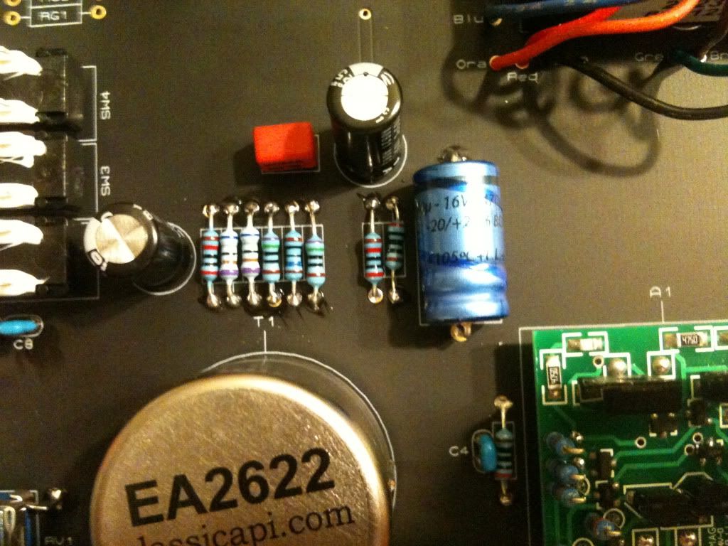
Oddly enough, I have a problem with mine. I have to turn both knobs up 100% full to get any signal. The mute works, the pad works, but when I use the phase flip I can hear a sound difference. I checked the value's on the resistors while setting up, do you see anything off that bat that could indicate a problem?
Oddly enough, I have a problem with mine. I have to turn both knobs up 100% full to get any signal. The mute works, the pad works, but when I use the phase flip I can hear a sound difference. I checked the value's on the resistors while setting up, do you see anything off that bat that could indicate a problem?
Yes I see your problem. You have a 200R and a 20k flipped with each other. R5 should be 20k and yours is 200R and vise-verse for R6. R5 is the feedback R which is why you have no gain.
Classic api VP25 not working properly after assembled : turn on no sound, so I turn the input and output gain to max out and got a very nasal sound. If you do have this problem just make sure you re-touched every solders joint and problem solve on most likely is the case and rarely dude to malfuntion of the tranformers fault. Hope that will help a liltle.
poiesznbeats
Member
- Joined
- Sep 6, 2012
- Messages
- 8
I just finished building my first VP312 VPR Rev A.... I was doing the tests recommended in the VP26 build manual and I'm concerned because I have failed two:
12.1.d
When I check impedance between "C" and "O" sockets for the op amp I get a value of 8.8...
12.2.a
When I have it plugged in my lunchbox (still no DOA installed), I get a value of -16V DC between "+V" and "C", the same value I get for "-V" and "C"
I don't want to install the opamp and fire it up because I'm worried about frying something. Any ideas? Or am I ok?
Thank you!
That measurement result is specific to the VP25-VP26 and has a different result for a VP312. You should get around 8.5 to 9 ohms as you are essentially measuring the DCR of the 2503's primary so it is a pass, not fail. ;Dpoiesznbeats said:12.1.d
When I check impedance between "C" and "O" sockets for the op amp I get a value of 8.8...
Try this one again while making sure the black lead for your DMM is on the "C" socket. Only move the red lead to measure the DCV.12.2.a
When I have it plugged in my lunchbox (still no DOA installed), I get a value of -16V DC between "+V" and "C", the same value I get for "-V" and "C"
poiesznbeats
Member
- Joined
- Sep 6, 2012
- Messages
- 8
Success! Thanks Jeff! I am all up and running!
Now the only thing left is what to do about THIS????? (edited for more clarity because I can't figure out how to post my photo)
My alignment on the push button switches was slightly off and I can't get the buttons on... or if i do they stick in the "in" position. I'm guessing I sat my pots too far down on the PCB as the switches are hitting the right side of the housing and faceplate. I have a feeling I'd need to desolder my pots to fix this. Surely I'm not the only one to make this alignment mistake. Or am I... Is there any easy fix?
Yeah, hard to say with no pics. When typing a reply to post, go just below the text box and click the "Attachments and other options" to post a pic.
If you did not follow the dry fit procedure before soldering in your pots, that could be the issue. Unfortunately, desoldering them will be the only fix.
If you did not follow the dry fit procedure before soldering in your pots, that could be the issue. Unfortunately, desoldering them will be the only fix.
poiesznbeats
Member
- Joined
- Sep 6, 2012
- Messages
- 8
Ahh.. here it is. I thought I did the fitting appropriately, but when it came time to add the switches I saw I was off. I'm going to try to get my second one built properly before I mess with this one again. I've never desoldered anything so I'm a bit apprehensive that I might damage something in the process, all for a cosmetic fix.
Attachments

I would assume that the PCB is farther away from the front of the L-bracket than the length of the 1/4" standoffs?
poiesznbeats
Member
- Joined
- Sep 6, 2012
- Messages
- 8
Yes. By the same amount as you can see in the switches. I did the whole fitting check when I soldered the pots to the PCB, but I don't think I was precise enough with the spacing of the 1/4" standoff, like you said. I ended up soldering the pots all the way down in their holes in the board, instead of up a little bit as I see in some photos now.
What am I risking by trying to undo this? I do have at least a functional preamp with no button caps... I would hate to ruin parts trying to get it right.
What am I risking by trying to undo this? I do have at least a functional preamp with no button caps... I would hate to ruin parts trying to get it right.
Well, with a decent desoldering tool like the Hakko 808 you will ruin nothing as long as you jump around and don't heat up the pots and PCB pads too much.
'Chung shows pretty well (I do to in the original VP2x Assembly Guide) how the pots should be dry fit into their holes and then the PCB assembled to the L-bracket with standoffs & faceplate fitted before soldering the pots in.
I myself would change it but it's your call.
BTW, you are not the first person to do this and I'm sure you won't be the last.
poiesznbeats
Member
- Joined
- Sep 6, 2012
- Messages
- 8
Ok, thanks Jeff, I will be building my second (hopefully correctly) and then try to fix the first.
One last question:
My tests with a dynamic mic are all great, but when I connect a condenser, I need to activate the pad AND have the gain all the way down, along with some output attenuation in order to get a sound that is not clipping. This is just with my voice, by the way. Is this normal? Have I screwed up some part of my phantom power? Again the dynamic mic works flawlessly with a full range of settings.
That doesn't sound exactly normal but depends on the mic maybe? The phantom would not cause this. I would build the 2nd pre and compare the end results. Can it be a converter setting or something? That has happened to many times to count.
Just wanted to drop some good vibes on this thread.
I'm an electronics noob for sure but I can take my time, be neat, and follow directions to a T. Finished assembling 2 gar2520's and 2 VP26's and they all powered on and sound AWESOME! Had to wait anxiously for my api lunchbox to arrive to see if anything I put together actually worked. I was considering building the 51X rack with PSU but I figured that between the pre, rack, and op-amps I was bound to screw something up and then go through hell troubleshooting. The two pre's act and sound the same as far as my ears and eyes tell me, I need to do some research and figure out how to do some further testing but overall i'm ecstatic. THANK YOU JEFF!! these pre's beat the hell out of my digi's and presonus stuff (8ch) and for 200 a pop, you make the home studio guy on a budget really happy!
Next project = mix buzz and 1176 clones : )... and more VP26's!!!
drumslinger
New member
- Joined
- Dec 21, 2010
- Messages
- 3
Hey guys was just gettting around to building my VP modules (with Rev B boards) 25, 26 and 312 but have run into a snag with one of the VP26 builds, no output sound. I traced the signal and everything seems to be ok. Unsoldered the transformer wires from the 2623 and tested the resistance (red/orange 14.6ohms, brown/black 22.3ohms and green/blue 22.3ohms). Checked the remaining 3 2623s (total of 5 VP26) and they ohm out the same. Retouched solder on all components (same issue, no output sound). Compared the working VP26 to the non working one and all the components are what they seem with color code and capacitor value. All 9 DOAs have been tested and work fine, even after swapping them out on the non working VP26. I'll report back more after i have swapped out a component I suspect.
drumslinger
New member
- Joined
- Dec 21, 2010
- Messages
- 3
**Update**
Faulty resistor found and replaced. 2nd VP26 up and running! Helpful stuff in this thread helped me pin point my problem. Many thanks guys!!
Faulty resistor found and replaced. 2nd VP26 up and running! Helpful stuff in this thread helped me pin point my problem. Many thanks guys!!
TheLavaBed
Member
- Joined
- Feb 23, 2010
- Messages
- 5
Can anyone help with what might be an obvious question? I just got around to building my VP26's, and I can't find Jeff's assembly instructions anywhere on the Classic API sight. I checked, and I don't have an email from Jeff with instructions (then again, I didn't email him and ask for one). I followed Chunger's instructions, and am 85% there, but I don't see any instructions on which resistors go in the spots for my stepped Grayhill potentiometer. Everything is assembled except those resistors (labeled RG1-RG11). Any help?
Thanks!!
Mike
Thanks!!
Mike
Similar threads
- Replies
- 5
- Views
- 956
- Replies
- 4
- Views
- 675
- Replies
- 11
- Views
- 6K
- Replies
- 14
- Views
- 1K