[BUILD] CAPI VP2X~500 Series~Preamp Kit~Official Support Thread

GroupDIY Audio Forum

Help Support GroupDIY Audio Forum:

This site may earn a commission from merchant affiliate links, including eBay, Amazon, and others.
Mike

Send me an email and I will send them right away. I send all docs out the morning or 2 after I ship. They often end up in spam folders.
 
Hi , I have just finished a pair of VP25...and was the easiest build I have ever done! I'm wondering if I could use my altran transformers from the mitsos 312 groupbuy, without modifying anything (zobel network?) using the VP25 boards from Jeff.

I have done some measurings comparing ed transformers and altran...and in the output transformer I have 8.3 ohms in my DMM in all the secondaries and 6.3 ohms in the altran secondaries.

Some help?
 
I have two questions !

just finished a new VP26 which works and sounds incredible! I f*cking love these things.

question 1). any reason why my led wouldn't be working? I tested it beforehand, using a led tester thing I have and it was great. I installed the R1 resistor and then installed the phantom switch as outlined by chung's pics and also the ammended instructions for rev b. The phantom power(and switch) works great (infact my tests today were all with a mic requiring phantom power). but the led simply doesn't turn on. I'm wondering if i missed something here...  (led polarization was most certainly correct when I installed).

LED was most certainly NOT installed correct. (to the other newcomers... take your time!)


lastly, I'm curious why the measured values on the O, C, V+, V- etc etc are always strange on my end. They're all over the place, (I've posted about it before with specific numbers but was never able to find out if its a problem or not). I mean, the things work, they sound great, so I guess its not a problem, I just don't like the feeling like i missed something or screwed up at the final step.  I use the fluke 177 as recommended in the assembly guide and have no other issues with it. It's not all that important, just wished i could confirm I've done a good job in some way other than just throwing it in the rack and getting sound and having all the knobs/buttons work.

 
CCW Stepped gain option = 25k reverse log? (original API 312 gain uses reverse log, thats why I ask)
the numbers look "loggy" to me.

Stepped gain R's

82ohm -----------------------RG1 or RG11?
120ohm
169ohm
249ohm
357ohm
511ohm
787ohm
1.24Kohm
1.97Kohm
4.99Kohm
14.7Kohm----------------------RG1 or RG11?

 
Yes, the VP Gainswitch will work perfect in an API style preamp circuit with a 20k feedback R. I also use a series 200R in typical fashion. I have the skiz attached although I usually email it out with a preamp or kit purchase. Maybe you just purchased the R's only? I remember an order like that recently.

The lowest 2 steps are 4dB and the rest are 3dB to the top. I would call it more linear than "loggy".  ;)
 

Attachments

  • 7_VP2x-Gainswitch schematic.pdf
    72.5 KB · Views: 18
Hey everyone, I hope someone can come in with any ideas here regarding my VP26 with the stepped gain option.  I built two simultaneously, one works mostly flawlessly, in as much as it sounds amazing but the led for the 48v doesn't light up.

The other one is radio silence.  Ironically enough, the led does light up when I switch it on, but that's about it.  I get signal spikes when I engage the mute and phase invert buttons, but nothing with the pad.  I went over the solder joints, and touched up a few that looked suspicious.  I have to say that I had a bunch of problems getting the wires from the output transformer soldered onto the PCB board, and worry that I may have damaged it.  I touched those up too.

Any thoughts or suggestions would be greatly appreciated!

Best,

Jeff
 
First, the non working LED is most likely in backwards.

The first thing to rule out is the opamp. What opamps are they and who built them? If they were kits, swap them in the preamps and see if the non working status follows the opamp or stays with the pre.
 
Thanks for the fast response Jeff!

'Chung and I built one of the op amps, one of the GAR 1731 variety and then I built the other on my own which is identical.  I swapped them out and there was no difference in the working unit.  I'll get around to flipping the led once the other unit is up and running, I don't want to have two down.
 
in my experiences, 98% of the problems I've run into are usually resolved when jeff kindly points out a simple yet stupid mistake I've made.
 
Exactly, and I think I can claim that here too.  After having switched the op amps to make sure the one in the "non-working" unit was operable, I went from component to component comparing them to make sure everything was in its right place, and more importantly, that their polarities were correct.  Despite the led in the working unit being reversed, everything in the "non-working" unit appeared to be installed with the correct polarity.  I flipped it over at that point, and did more investigations of the solder work. I touched up a few things which I honestly doubt were bad, but did so anyway.

Here's the thing, when I went to test it, I noticed that I hadn't put the op amp back in from when I had switched them.  I'm a total, total newb when it comes to this stuff, the only other things I have soldered were back in eighth grade shop and none of them worked.  My point here is that I tend to be a little timid with the PCB board and components.  In putting the op amp back in, it clicked a little more firmly than I had originally set it into the millimax sockets.  Between not putting it in fully, and the slight angles on the pins, I don't think it had originally been making contact.

Having done this, when I fired it up it worked fully and perfectly and sounds identical to the first one.  The stereo set is up and running and I couldn't be more pleased!  Thanks Jeff, for the help on the led and getting me moving in the right direction!

Jeff
 
Thank you, Jeff, I had not seen that!  I stand in direct violation of rule number one, read all the directions first!  Thanks again!
 
Hey gang,

I'm building my first VP26, and so far so good (I think). I'm unsure how to install the LED. Does the shorter lead go where the arrow points, or vice versa?  Maybe that's been answered, but I couldn't find it in this thread.

Thanks,

C
 
Help Please!
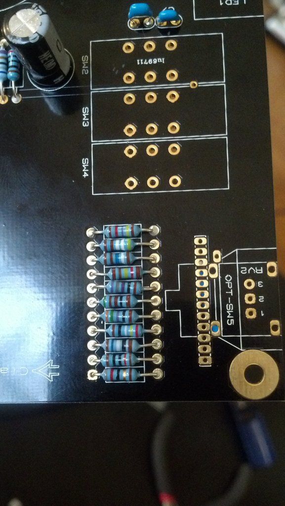
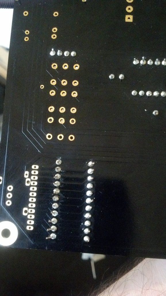
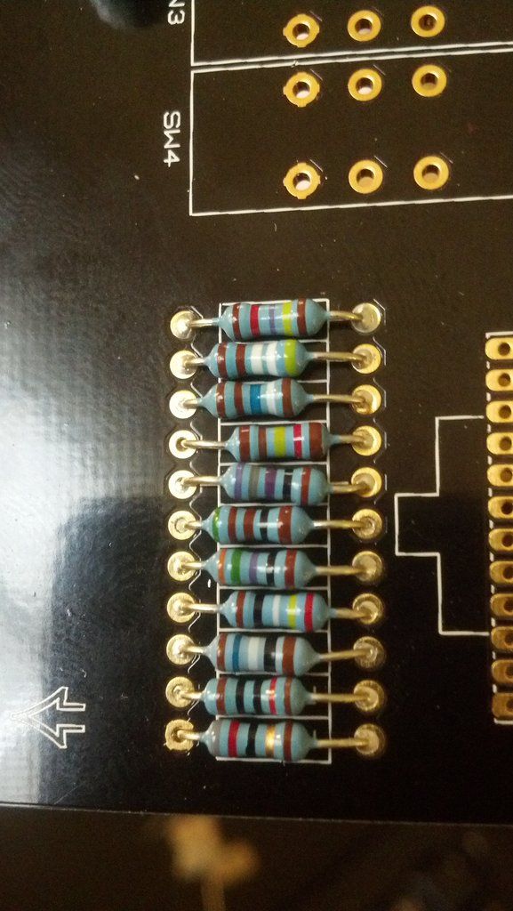
I have started on my VP 26 build (and I'm a bit of a noob).  I have the stepped gain option and put in the RG resistors and measured the resistance of the switch pad to the left of RG11 and the switch wiper pad, and my resistance continues climbs up and sometimes goes down.  I inspected my soldering carefully and it looks OK.  Included are some pics. 

Could there be something else that's causing the strange readings, or should I just retouch all the solder joints.  Thanks!

photobucket-45926-1361134365183_zpsf15e9874.jpg


photobucket-38498-1361134349311_zpsa8697b9d.jpg


photobucket-1403-1361134314596_zps6ac6254f.jpg


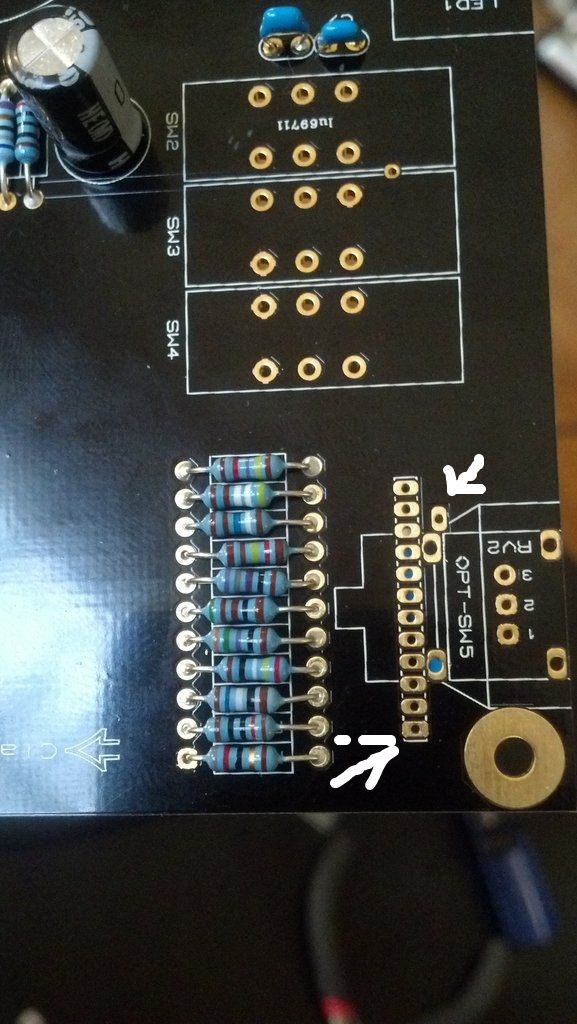
Below are the two points I measure - is this correct?
23373ac5-1b23-432a-9b5e-5266d56db894_zps8d2edb2d.jpg
 
tfunster said:
... and measured the resistance of the switch pad to the left of RG11 and the switch wiper pad, and my res...
Below are the two points I measure - is this correct?
No. Without the switch installed there is no connection to the wiper pad. Measure total resistance of this series string between the switches outer pins.
 
Harpo said:
tfunster said:
... and measured the resistance of the switch pad to the left of RG11 and the switch wiper pad, and my res...
Below are the two points I measure - is this correct?
No. Without the switch installed there is no connection to the wiper pad. Measure total resistance of this series string between the switches outer pins.

Thanks Harpo - when I measure it like you say, I do get 25k.  However I was going by this bit of instruction in the guide that Jeff sent me: "Before moving on, using your DMM, probe between
the switch wiper pad and the switch pad just left of RG11. You should have around 25k +."

So, the guide is incorrect?  Or did I just read it wrong? 
 
Back
Top