


maxwall
Well-known member
- Joined
- Nov 17, 2004
- Messages
- 1,134
I'm converting a Scully 280 discrete transformer coupled head amp into a preamp , but it runs on a postive grounded supply 24Vdc. in other words the + side of the power supply is grounded to the chassis rather than the negative side. This head amp was used for the Scully reel to reel recorders , and this one came from a parted out 2 track deck.
The scully 280 has the following transformer compliment
UTC A18 15K:80K Line Input
UTC A39 600:2K Mic input
Freed 600:600 output
Question : What proper conversion must be done to the Scully's XLR mic and line input and outputs to ensure that standard XLR equipment like a condenser microphone will not be harmed when connected to the unit.
I'm guessing that changing the wiring positions on the connectors of the Scully to match EIA XLR standard must be done but I'm not quite sure. I rarely come in contact with equipment running on a positive ground.
I don't want to screw up any XLR gear experimenting either. I would like to get this right the first time.
Also, I made a slide in cassette power supply for this scully 280 by utilizing the compartament normally
occcupied by the oscillator board. This board is not needed for turning this unit into a mono preamp. Nevertheless, how do I tie the saftey ground on the center pin of a three prong 115Vac power supply cable. It would normally go to chassis ground but in this configuration....It would cause a short if it were connected to a positve ground. I'm thinking a safety ground on the power supply may not work in this case, any ideas ?
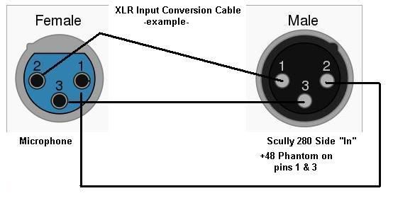
The Scully XLR connector is as follows
Pin 1 - positive chassis ground (+) zero reference
Pin 2 - Negative signal , Hot (-)
Pin 3 - Cold
The EIA XLR Standard is
Pin 1 - Negative Chassis Ground or Shield ( - )
Pin 2 - Hot (+)
Pin 3 - Cold (-)
Here is a input conversion cable I thought might fix this problem. The XLR output cable would likely follow the same scheme. Would I be better off with a polarity reversal switch than a conversion cable.
Can someone check my work ?
The scully 280 has the following transformer compliment
UTC A18 15K:80K Line Input
UTC A39 600:2K Mic input
Freed 600:600 output
Question : What proper conversion must be done to the Scully's XLR mic and line input and outputs to ensure that standard XLR equipment like a condenser microphone will not be harmed when connected to the unit.
I'm guessing that changing the wiring positions on the connectors of the Scully to match EIA XLR standard must be done but I'm not quite sure. I rarely come in contact with equipment running on a positive ground.
I don't want to screw up any XLR gear experimenting either. I would like to get this right the first time.
Also, I made a slide in cassette power supply for this scully 280 by utilizing the compartament normally
occcupied by the oscillator board. This board is not needed for turning this unit into a mono preamp. Nevertheless, how do I tie the saftey ground on the center pin of a three prong 115Vac power supply cable. It would normally go to chassis ground but in this configuration....It would cause a short if it were connected to a positve ground. I'm thinking a safety ground on the power supply may not work in this case, any ideas ?
The Scully XLR connector is as follows
Pin 1 - positive chassis ground (+) zero reference
Pin 2 - Negative signal , Hot (-)
Pin 3 - Cold
The EIA XLR Standard is
Pin 1 - Negative Chassis Ground or Shield ( - )
Pin 2 - Hot (+)
Pin 3 - Cold (-)
Here is a input conversion cable I thought might fix this problem. The XLR output cable would likely follow the same scheme. Would I be better off with a polarity reversal switch than a conversion cable.
Can someone check my work ?
")