API-ish Mic Pre Project

GroupDIY Audio Forum

Help Support GroupDIY Audio Forum:

This site may earn a commission from merchant affiliate links, including eBay, Amazon, and others.

synthetic

Well-known member
Joined
Oct 23, 2004
Messages
218
Location
Glendale, CA
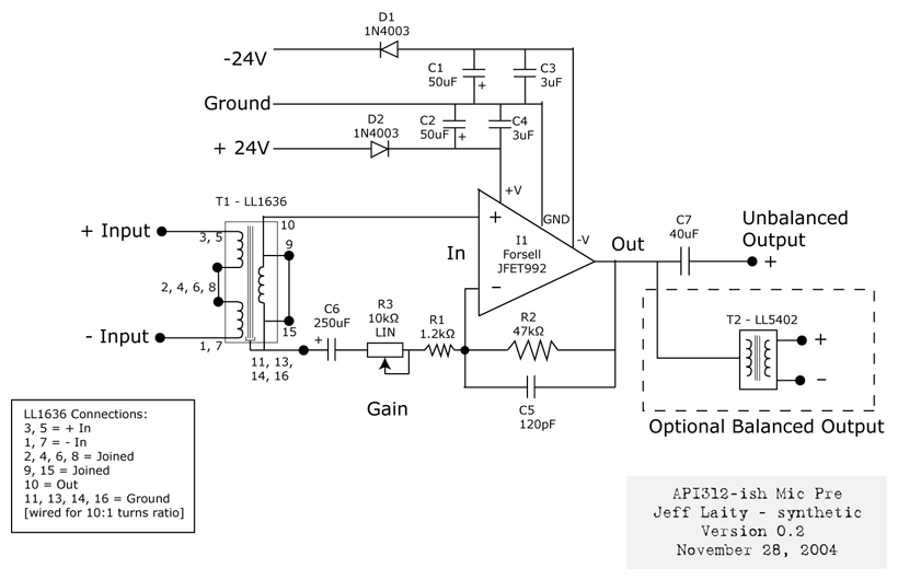
Here's my latest project, a mic pre based on the API 312. I borrowed pieces from several pres to come up with this circuit:

http://www.jefflaity.com/misc_pix/forsell_api_preamp.gif

Here's the parts list so far:

http://www.jefflaity.com/misc_pix/forsell_api_parts.xls

I'm using a Luhndahl 1636 for the input transformer and a Forsell JFET992 as my discrete op amp. The output cap is a massive 40uF Polypropylene cap. I don't have an output transformer yet, I'm just going unbalanced for now.

I used a 10k linear pot for the gain instead of the 25k rev audio pot that the API uses. I don't get a lot of gain out of the preamp yet, and I'm not sure if this is a design flaw or a build flaw. I suspect the latter.

The power supply is a Peter Green preamp supply. I used 24V regulators to make it into a 24 volt supply.

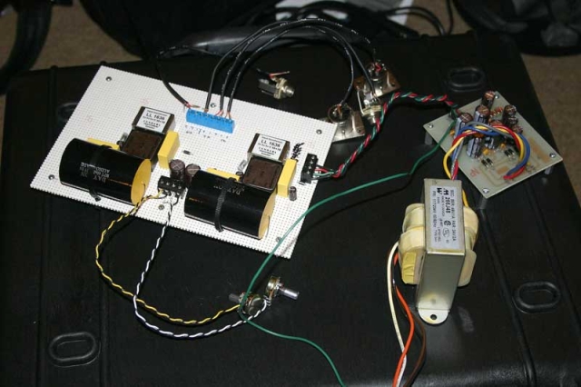
Once I get this up and running I hope to create a web page about the construction. It seems like a nice project for a beginner (of which I definately categorize myself). For now, here's a picture of the project in process:

api1.sized.jpg


More pics here:

http://www.jefflaity.com/gallery/API-Forsell-Preamp

Let me know what you think, -jl
 
Let's see if in these months here I learnt something...
I suspect R2 should be lower value, with 10k the maxium gain from opamp (excluding transformers) is 3 or slighty less than 10dB.
Hope this is correct, if not erase me!

Frank
 
I suspect R2 should be lower value, with 10k the maxium gain from opamp (excluding transformers) is 3 or slighty less than 10dB.
:thumb:

In addition, you better use a log pot.

For the unbalanced out, I recommend a small resistor in series (20 to 50 Ohm), which will improve stability when driving long cables. If you connect pin 3 through a similar resistor to ground, you get a simple balanced out. You don't need (don't want, actually) the resistors with the tranny out.

No phantom power needed?

Samuel
 
Hi synthetic

You have very low gain because the resistors are wrong.
R1 should be 10K and R2 should be 10 ohms [NOT 10K]
Also for better low freq response I would use a higher value for C6.
C5 can be significantly lower, in the region of 10 to 47 picofarad. Use a scope to determine the right value for maximum stability.

chrissugar
 
Thanks everyone. I was using values from Pat M's mic pre. I'm glad I didn't pay $300 for his design -- I kinda suspected I needed more in the feedback loop. However, looking at the API 312 schematic, they have a 20k resistor where I put my R1:

http://www.jefflaity.com/misc_pix/api312schem.gif

So I'll experiment with R2 first. I hope I have some smaller resistors lying around.

Phantom power is phase 2. I wanted to get the pre working with dynamic mics first. Once that's happening, I'll add a phantom power and phase switches. Baby steps. :)
 
That's basically Project 2 and you should find a few variants of circuit layout around the net from various Group DIY members.

Fabio and Joe Malone and the old Project 2 page etc ...
One thing that I included on the PCB was a cap/resistor network after the Mic trafo so you could adjust for square wave resp. It might also be cool to have a cap after the Gain Block. I have been told that there can be some issues when powering up on some gain blocks and DC offset. This offset can cause a problem in some Gain Blocks that may rtesult in a failure.

err
that's all I can think of for now.
 
Pat M?
That better not be who I think it is!
:evil: :twisted: :evil: :twisted:
:twisted: :evil: :twisted: :evil:
:mad: :sad: :mad: :sad:
:shock: :cry: :shock: :cry:
 
It is. Someone dropped his preamp schematic in my inbox. I can't believe he wanted $300 for this bad reworking of an API schematic, what a con.

So I swapped out my resistor before the gain pot (R2) to a 20 ohm, and now it's all screwed up. I only hear signal when the gain is turned all the way down, and it has a lot of hum and distortion at this setting. And now I'm out of town for the rest of the week and can't troubleshoot. Grrr. More experiments with gain this weekend, perhaps.
 
I'm not sure which ground connection you mean. The input transformer shouldn't be connected to ground? Or the return from the gain pot? I disconnected the ground on the output jack already, that was humming like a lift operator convention.
 
So here's the latest version with cjenrick's gain block:

Forsell_API_preamp_02.jpg


I've tried R1 as 10 ohms and 1200 ohms and both times I get hellish feedback from hell. It's much louder on channel 1 than 2, which makes me think I screwed something up in there, or maybe it's a problem in the design? Turning the gain pots slightly changes the pitch of the distortion. Audio is quite badly distorted. Any advice, aside from checking for shorts and bad connections?

Thanks, -jl
 
> no ground required on the input.

It is required. Otherwise the feedback has no idea where ground is, and the output voltage is undetermined.

R2 for a 25K log is reasonably about 250Ω. The same will work with a linear, but will be super twitchy as you approach maximum gain.

The output jack Ground should NOT wander all over the input nodes, but bee-line straight back to the power supply.
 
I solved the feedback problem -- the gain pots were attached reversed. Now, I have a problem where the input signal distorts when it reaches a certain level. It's a normal level, then if I say "check" a little louder, the level jumps way up and it distorts. Perhaps this is connected to the problems that PRR mentions below:

[quote author="PRR"]> no ground required on the input.

It is required. Otherwise the feedback has no idea where ground is, and the output voltage is undetermined.[/quote]

Where in my circuit do I send it to ground? Before C6 like the API?

R2 for a 25K log is reasonably about 250?. The same will work with a linear, but will be super twitchy as you approach maximum gain.

You suggest 25k log for the trim pot and 250 ohm for R2? Would that give me 10:1 gain?

The output jack Ground should NOT wander all over the input nodes, but bee-line straight back to the power supply.

Connect the output ground to my star ground? I had a lot of hum when the output ground was connected, but I'll try that.

Thanks for yor help, -jl
 
I tied the input to ground before C6 and this fixed the distortion problem that I was talking about. It seems to be working pretty well now. Thanks PRR.

I would like to have more range in the gain pot. The lowest setting is still pretty loud (with voice through a Shure Beta 57). I might try a 25k log pot for the gain, then change R2 to 100k or 200k. Or should I experiment with R1?

Thanks again, everyone.
 

Latest posts

Back
Top