Relay controlled potentiometer

GroupDIY Audio Forum

Help Support GroupDIY Audio Forum:

This site may earn a commission from merchant affiliate links, including eBay, Amazon, and others.

Dusty Circuit

Well-known member
Joined
Dec 23, 2008
Messages
79
Location
Sweden
Hi

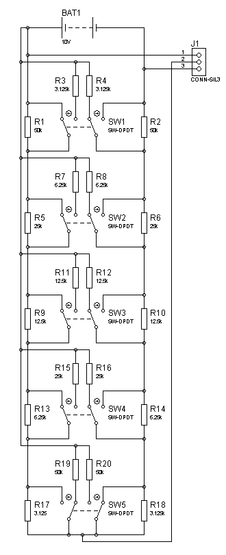
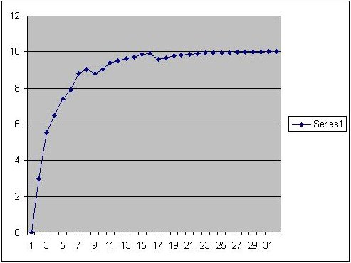
I am attempting to construct an logarithmic potentiometer using relays and resistors. The goal is to use these circuits to control practically anything with a pot and store the setting for later use. I have successfully constructed an linear one using an article in EDN-magazine as a base. However, a logarithmic one turned out to be more difficult. I used the EDN design as a base for this as well but added some resistors in a T-network (?) fashion. This seems to work but i got some "bumps" when i plotted the graph. Does anyone have a suggestion to what's causing this? I have used Rtot/2^n to calculate the values for the resistors.

EDN article

Schematic of the logarithmic pot:
log2.jpg


Graph of the result. y: Voltage x: Step (binary)
graph.JPG


Best Regards,
Hampus
 
burdij said:
You might want to look in this extensive thread for some ideas, particularly posts by Mikkel C. Simonsen (mcs):

I have only worked on linear "pots", that can be made log or antilog by selecting the correct steps. But this may not offer steps that are small enough. I have also made attenuators with fixed dB steps, but they are attenuators not pots...

Best regards,

Mikkel C. Simonsen
 
Hi Mikkel

I sent you an e-mail a couple of hours ago regarding this. So you solved the problem in software then? Can you give me an example of the number of steps you get from, say a six relay configuration? You mention a friend i the other thread, has he made any progress with his pot?

I have now gotten to know the circuit a little better and have fixed most of the bumps in the earlier graph (it is actually a lot smoother now). I also noticed that you can change the curvature of the pot by putting a resistor instead of a link between the middle resistors and one of the terminals on the pot (at the positive side of the battery in the schematic). By decreasing the resistance you get a more linear curve. Now I have fitted an 6.25K resistor here witch smoothen the curve. I will post a graph when I get the time. However, the overall resistance of the pot is now 96k instead of 100k. A 4% error is... okey i guess but i aim for perfection. ;) I think tweaking of this resistor can be fruitful. My biggest problem now is the fact that these graphs take a long time to plot as i have to feed everything from Proteus to Excel manually and do all the stepping by hand. Anyone now a workaround on this?

 
It would be interesting to know what you intend to do with this pot; someone may come with another idea. The big question is: do you really want a potentiometer or an attenuator?
Dusty Circuit said:
I have now gotten to know the circuit a little better and have fixed most of the bumps in the earlier graph (it is actually a lot smoother now). I also noticed that you can change the curvature of the pot by putting a resistor instead of a link between the middle resistors and one of the terminals on the pot (at the positive side of the battery in the schematic). By decreasing the resistance you get a more linear curve. Now I have fitted an 6.25K resistor here witch smoothen the curve. I will post a graph when I get the time. However, the overall resistance of the pot is now 96k instead of 100k. A 4% error is... okey i guess but i aim for perfection. ;) I think tweaking of this resistor can be fruitful. My biggest problem now is the fact that these graphs take a long time to plot as i have to feed everything from Proteus to Excel manually and do all the stepping by hand. Anyone now a workaround on this?
It is indeed a known fact that one can "twist" a potentiometer's law by adding a resistor between the wiper and one of the extremities, but it is not seen as a constant resistance anymore.
 
iomegaman: Thank you for the suggestion but I aim for a purely discrete path.

abbey road d enfer: The applications for this type of pot is quite wide. I want to use it to control EQ:s and basically anything with a pot in it. It is not to be confused with an audio attenuator this i an equivalent of pot (if it works) .
 
Hi!

Progress is very slow right now. I have made some test on board but I run in to problems with varying impedances and all sort of problems. I have however successfully constructed an attenuator with variable curves and no "bumps". This needs to be buffered though since impedance varies with steps. I guess it could be used in a pan-circuit perhaps. It uses two resistors per n-step. I will post some more information about that and a PCB for the linear pot soon.

Best Regards
Hampus 
 
Back
Top