Federal AM-864

GroupDIY Audio Forum

Help Support GroupDIY Audio Forum:

This site may earn a commission from merchant affiliate links, including eBay, Amazon, and others.
drpat


i have already check R1 measures 2.25 Meg

as a side note i did find that if i removed R1 the oscillation stopped. if the c1 was bad would you see the effect in att mode, when in att mode their was know release is this due to r1 not being in Parallel with C1.

I will recheck with R5 full clockwise , and take reading ref to ground ..

Should the federal be on while taken the resistive readings.

I will post 2morrow

thanks again drpat

skal1
 
Hey me again here are the new values follow your set up  method.

V4

pin 1:0 ohms

pin 2: 300k

pin 3 : 1.5 ohms

pin 4+5 : 2.37meg

pin 6: 45k

V1

pin 1to5: 0 ohms

pin 4 :2.30meg

pin 6: 1.032

pin 8:27.6k


V2

pin 1to5: 0 ohms

pin 4 :2.30meg

pin 6: 1.032

pin 8:27.6k


I also replaced c1 , it had no effect on the oscillation with threshold and current at max. so what i did next was to parallel the two 1uf capacitors  to make 2uf and the oscillation  was gone  ???.

does this rule out the c1 as the suspect component i think so what , do you think?

skla1


drpat said:
These are the readings that are off:
V4 pin3: your current control is probably mis-set. Re-align your current control and lock it down for now.
manual says set to 2.5 vdc correct?

drpat said:
V4 pin4&5: This reading points to R11 being high... my guess is that it reads in the neighborhood of about 120K, which would be waaaaaay out of spec. Can you verify that R11 is within tolerence? If it really is out that far... replace it.

Will check and replace 2morrow

drpat said:
V1&2 pin4: a tad high. replace R1 with something that's in tolerance to bring this within specs.

Will check and replace 2morrow

drpat said:
V1&2 pin8: Did you change your plate resistors BACK to 12K?

I did replace plate resistors back too 12K , so that  is ok.
drpat said:
Another thing that you can try is croc-ing another 22µF cap in parallel with the single 22µF cap AFTER L1 to give you 44µF total. Or just put one in permanently and leave it there.

Will try that 2morrow

and thanks again, i think where really close to finding the problem

skal1
 
OK did those exchanges

R11{46.7k

R1  {2.08 meg

V4 pin 4+5 : 2.07meg
    pin 3 : 167 ohms

V1 pin 4 :reads 2.01meg

V2 pin 4 :reads 2.01meg

still oscillates though. ???

skal1
 
drpat said:
What resistance readings are you getting from V3 pin1 to ground, and V3 pin4 to ground?

V3 pin1 to ground, 470 ohms

V3 pin4 to ground ,471 ohms


drpat said:
Did you add the extra capacitance after L1? You could just use a single 47µF cap to replace both of the 12µF caps like I did.

yes ,just put a 25uf across the one that was their.

drpat said:
You might need to match V1 & V2 better. You tested all of your tubes, right?
i have no tube tester.how can you match the tubes , can they be matched in circuit ? what should i be looking for in a good match... current /voltage...


skal1
 
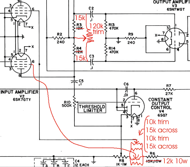
The addition of a balancing circuit on the plate side would be simple and useful.  I believe several people have presented one here before.  Won't solve a drastic mismatch, but lets you fine tune one that's already reasonably close.  Some limiters come with this already (BA-6A), Gates used shorting jacks in the path to insert current meters for in circuit measurements. 
 
rafafredd said:
here´s a plan... don´t mess with the cathode:

balance_mod2.gif


sorry for the mess, but it should be readable.

so something like this should work..

skal1
 
Back
Top