Unusual pan-pot solution

GroupDIY Audio Forum

Help Support GroupDIY Audio Forum:

This site may earn a commission from merchant affiliate links, including eBay, Amazon, and others.

cuelist

Well-known member
Joined
Aug 21, 2004
Messages
248
Location
Sweden
From Doug Self's site:

To give smooth stereo panning without unwanted level changes, the panpot should theoretically have a sine/cosine characteristic; such components exist, but they are prohibitively expensive and so most mixing consoles use a dual linear pot. with its law bent by a pull-up resistor, as shown in Fig 7a. This not only gives a mediocre approximation to the required law, but also limits the panning range, since the pull-up signal passes through the wiper contact resistance (usually greater than the end-of-track resistance) and limits the attenuation the panpot can provide when set hard left or right.

This limitation is removed in the Soundcraft active panpot shown in Fig 7b by replacing the pull-up with a negative-impedance-converter that modulates the law-bending effect in accordance with the panpot setting, making a close approach to the sine law possible. There is no pull-up at the lower end of the wiper travel, when it is not required, so the left-right isolation using a good-quality pot. is improved from approx -65dB to -90dB. This concept has also been made the subject of patent protection.


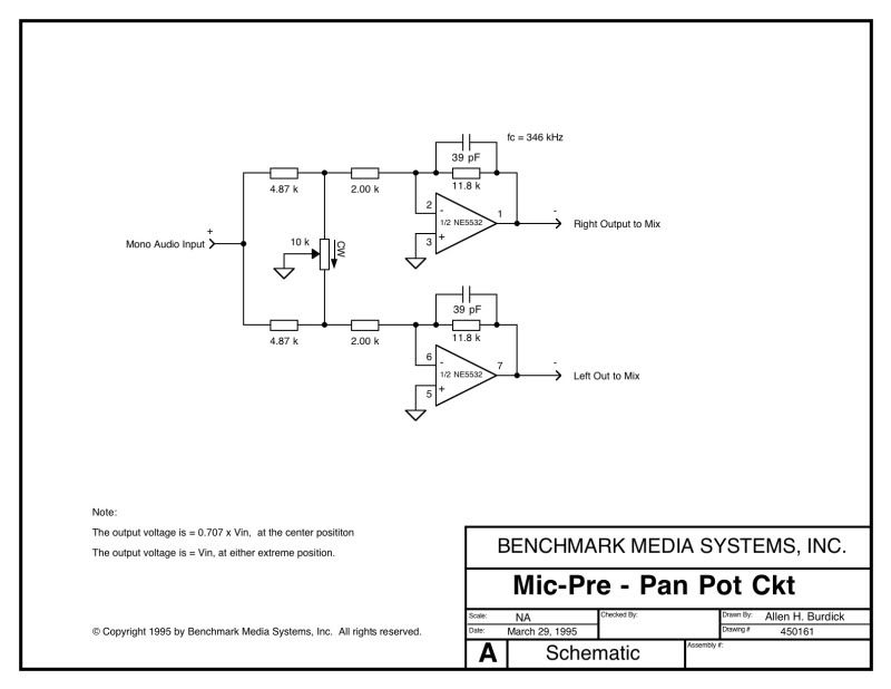
See the actual circuit (in attachment) - if it is as good as he says, why isn't it commonly known or used?


Attachments

  • NIC_PanPot_SC8000.jpg
    NIC_PanPot_SC8000.jpg
    21.8 KB · Views: 362
It is commonly known.

However, when it comes to using it, it all comes down to the economics. When you are putting out a commercial product you will save even a single resistor if you can get away with. So, you make a decision whether your product can get away with a mediocre panning or you need to incorporate the active solution.
 
The circuit was used in some Soundcraft consoles in the 90's. If I remember correctly it was patented (or at least they tried to patent it). I have never tried it but I have heard that it can be difficult to get it stable. I guess the Self/Soundcraft circuit tries to solve the problems of the two standard configurations:

1. Dual linear potentiometer. Easily available but you need a resistor between the signal and the pot wiper to get a correct curve. As a result the off-attenuation is quite bad (the curve bending resistor and the potentiometer end resistance form a voltage divider).

2. Dual potentiometer with one positive log section and one negative log section. Not easily available and the curve accurary is not as good as with linear potentiometer.
 
cuelist said:
sahib said:
It is commonly known.

Know any other commercial product using it?


I don't know. I did not particularly investigated which product uses it but the fact that I have known it for years means it must be even more common knowledge to those who practice audio electronics more than I do.

However, if the result it offered were overwhelmingly greater than the topology that is mostly used, then I am sure the other (mixing console) manufacturers would have used it (by licence if it was patented), or at least tried to solve it in more elaborate ways of their own, because there would be a commercial advantage. Say you have additional 20 pence on that scheme, 24 channels on the console and you are manufacturing 5000 consoles. A lot of cash to weight against the commercial advantage it  offers.
 
Patent number GB2214372A. It has now expired and it was patented in UK only.
http://gb.espacenet.com/


I can testify to the fact that it works remarkably well, in particular it offers unparalleled left/right separation compared to the dual Lin pot configuration, because the residual wiper resistance is disconnected. The only problem of stability is when the wiper looses contact with the track, which may happen when they wear out.
As to why it's not been used by other manufactures, I reckon the combination of british patent (considering most of Soundcraft's competitors were British) and the "not made in-house rejection syndrome" explain it.
 
there is also this from 1995

panpotactive.jpg
 
kambo said:
there is also this from 1995

Yes, and quite possibly the worst possible pan-pot arrangement. Here you are completely at the mercy of the pots wiper to track resistance. The passive version of this one is common in the dirt cheap mixers.


This arrangement has two major drawbacks:
a) The L/R separation is not very good because of the wiper-to-track resistance
b) The attenuation introduced requires a buffer or operating the busses at reduced level
BTW, with the actual values, the center attenuation is only 1dB compared to full L or R and there is 2.5dB of gain.
 
abbey road d enfer said:
The only problem of stability is when the wiper looses contact with the track, which may happen when they wear out.
That problem could be countered by adding a wiper-cold resistors in parallel to pot. That would change the pan-law, but stability would be improved.
 
That arrangement actually goes as far back as late late 60s / early70s. Cost effective, single pot hi-fi application.  However, better version would be to use a reasonably matched dual pot.
 
tv said:
abbey road d enfer said:
The only problem of stability is when the wiper looses contact with the track, which may happen when they wear out.
That problem could be countered by adding a wiper-cold resistors in parallel to pot. That would change the pan-law, but stability would be improved.
The 2K Rin resistors are already in parallel to the pot with the resistors other side connected to op-amps virtual ground, giving +2.53dB @ center and +3.55dB @ either extreme position.
 
tv said:
abbey road d enfer said:
The only problem of stability is when the wiper looses contact with the track, which may happen when they wear out.
That problem could be countered by adding a wiper-cold resistors in parallel to pot. That would change the pan-law, but stability would be improved.
That would be a combination of negative-and-positive resistance, which would increase the noise gain of the stage, while still not ensuring stability in the worst case (open wiper), but, yes, there is a possibility to optimize this configuration.
 
Hello there!

Can somebody explain how to calculate the opamp configuration in the first post? I have never seen negative and positive feedback at the same time and cant get my head around the numbers. The non-inverting model is not working on this one! So please help me on this!

Thanks in advance!

Wolfgang
 
Consider V1 the voltage at the non-inverting input. The output voltage is V1.(1 +R2/R3).
Let K be the percent of rotation of the pot, so the bottom is kP and the top is (1-k)P
Let Rp1= kP//R3 and Rp2=kP//(1-k)P
According to the superposition theorem, V1 is the sum of the input voltage Vin through the voltage divider constituted by the resistance between top and wiper and Rp1, and the output voltage Vout through the voltage divider constituted by R3 and Rp2.
Then V1= Vin.Rp1/[Rp1+(1-k)P + Vout.Rp2/(Rp2+R3)
If you develop, you end up with an expression that will give you headaches for the next millenium, but fortunately you can solve it for mid-rotation relatively easily and that will give you the values for the desired center attenuation.
OTOH, if you sim it with LTSpice, you'll see the nice graphs in about 10 minutes and you'll be able to play with the values.
 

Attachments

  • active panpot.jpg
    active panpot.jpg
    17.2 KB · Views: 32
Thanks for your fast reply!

So the gain of the amp is constant, set by R2 and R3.

What changes is V1 by rotating the pot. which influences final output voltage.
What i dont understand is how you get to Rp1 and Rp2. they are substitution for what resistances??

I have to think about it more than once ! :)

Thanks a lot for explaining so far!

regards,
Wolfgang
 
your help is much appreciated!!

I can see now how the resistors are paralleled! Your formula is clear now, i had problems with all the letters. ;)

Do i overlook something or is there a problem with two unknown values if a want to calculate Vout without knowing V1 and vice versa?

I have to look if i can translate the formula to Vout= Vin*xxxxxx

I think i will go the LTSpice route to get my numbers right.

Thanks a lot,

Wolfgang
 

Latest posts

Back
Top