Relay True Bypass

GroupDIY Audio Forum

Help Support GroupDIY Audio Forum:

This site may earn a commission from merchant affiliate links, including eBay, Amazon, and others.

ricothetroll

Well-known member
Joined
Jul 5, 2005
Messages
325
Location
Bruxelles
Hi !

I just drawn that schematic :

Relay_True_Bypass.jpg


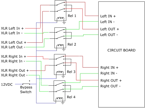
That's in order to have a true bypass on my GSSL, controlled by a single switch. The idea of relays is that it's quite impossible to find 8PDT hardwire switch.

I found that relay that migt work for it :
http://be.mouser.com/ProductDetail/Tyco-Electronics/D3002/?qs=HTr%252boA4jRiklpi5eOqZK2A%3d%3d

As it's the first time a draw a schematic with relays, I'd like to have some opinions on the design, and also, feel free to comment about the main idea of it !

Thanx in advance !

Eric
 
So, why does it have to be one relay?  Four separate relays would be easy to find, the cost should be less and channel cross-talk might be lower.
 
So, why does it have to be one relay?  Four separate relays would be easy to find, the cost should be less and channel cross-talk might be lower.

Hm, Rel1...4 are separate relays, all controlled by one switch !

you might want to add a diode across the coil of the relay to protect it.

do you mean something like this ?
relais_0001b.gif

(I'll have a "hardware" switch instead of Q1)
 
I have done this before in products.  I power the relay(s) from a separate unregulated PS that has a small reservoir capacitor so it collapses quickly after power is removed. A short delay after power up gives the circuitry time to settle before connecting. 

Yes, diodes are commonly used to catch inductive spikes.

JR
 
That diode is not for protecting the relay but for the active device that controls it. It prevents inductive kick dumped back on the active device and damaging it. Even if you are controlling it with a mechanical switch, it is still a better practice to use the diode.
 
Hm, Rel1...4 are separate relays, all controlled by one switch !


do you mean something like this ?
relais_0001b.gif

(I'll have a "hardware" switch instead of Q1)
what is the 2n2222 transistor used for? is this component necessary? is enough with the diode to protect the relays? Where does the center pin of the transistor go? Thank you so much
 
Depending on space, something like this from AliExpress, maybe ? Cheap enough.

1631879414784.png


Other than that, I usually prefer relays only on 'output' for switching between 'bypassed signal' and 'compressed' signal. Thus , even in bypass , the compressor attenuates the signal and doesn't have to suddenly 'kick in' when switching to processed signal. Could be undesirable when set to heavy compression and a lot of makeup gain dialled in.
 
Have you noticed it is tagged as "obsolete"? Anyway it's a quite common type of relay, you can find it under many brands, Omron, Panasonic, Finder...
As it's the first time a draw a schematic with relays, I'd like to have some opinions on the design, and also, feel free to comment about the main idea of it !
You have drawn a full bypass implementation, which is quite often not necessary.
As Script mentioned, you could switch the outputs only, would save a few bobs, and probably be more ergonomically pertinent.
 
Just make sure with a GSSL that you do NOT power the relays from the onboard 12V rails. That can mess up your CV signal. Power thru a resistor from 15V.
 
Back
Top