


jdbakker
Well-known member
Hi all,
In designing my discrete mic pre I've run into some difficulty in determining the gain structure, and I'd like to ask for your input.
First, this is what most common microphone preamplifiers look like:
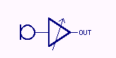
The core is a variable-gain amplifier, where the gain is usually varied by changing the amplifier's feedback resistor network. While this does work, one of the problems with this approach is that it sounds differently in different gain settings. This is because the change in feedback also (generally) impacts the amplifier's closed-loop frequency response and thus its distortion signature. In addition to this the variable part of the feedback network is necessarily connected to rather sensitive nodes in the amplifier, and the wiring to a gain switch or pot can easily pick up noise.
A cascaded-gain mic pre avoids this by having fixed-gain amplifier blocks with variable attenuators in between:
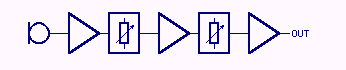
(Note that I don't claim this to be a new approach. Some of the oldest amplifiers worked like this, and this method has been discussed here a few times in the past, like in posts by pstamler, bcarso and Samuel Groner in this very interesting thread, and here by PRR).
But now the question is: what should the gain be for the amplifier blocks, and what attenuation range do we need for the attenuators?
We don't have enough information yet to be able to say anything. What should the gain range be? For the time being I've picked 20-60db. Other than that we want the usual goodies: high dynamic range, low noise, particularly in low-gain configurations.
I've already picked a few numbers out of the air. I want to be able to use common low-noise SMD transistors, most of those have a maximum VBE of ~45V. So call the maximum output swing of each amplifier stage +/-20V, or 14VRMS, or 23dBV. Most common transformerless mic pre recipes are differential on the inside, let's keep the entire pre differential, just for laughs. Differential swing is double the single-ended swing, or 29dBV.
Now, from my own experience and from what others have posted here, it would be nice if the pre could handle occasional 1VRMS (ie 0dBV) signals. To not clip for such levels the gain of the first stage should be no more than 29dBV-0dBV=29dB. Then again, noise theory says that if it has sufficient gain the first stage will dominate noise performance, so gain shouldn't be very much lower than this.
The other two (fixed) gain blocks are both preceded by a variable attenuator. There is little point in having a minimum attenuation higher than 0dB, as that would be wasting gain in the highest overall gain settings. On the other end of the scale the maximum attenuation should at least be equal to the gain of the following gain block. If it would be any lower, then for strong signals the second (or third) stages could clip even when the first one doesn't, and that would only waste dynamic range.
My current plan looks like this:
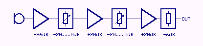
The final attenuator scales the output level of the third stage back to normal studio levels. As said before the maximum unclipped output of the gain blocks is 29dBV or a little over 31dBu into 600R; the 6dB attenuator leaves a more manageable 25dBu. Full gain range is 20-60dB, as specced.
How does this look so far?
One of the issues left to be decided is the attenuator impedance. Too high and it will kill low-gain noise performance, too low and the attenuators will function as space heaters. While I have sim-tested the gain blocks with a 200R differential load my current plan is to have the attenuators be 600R. At that resistance a sine that's just below clipping will have each attenuator dissipating just over a Watt, and the total noise figure in the lowest gain setting would be 4-5dB. This can be improved somewhat by implementing Samuel Groner's suggestion to switch out the third gain block for gains of 40dB and lower, but that would probably affect the sound of the entire chain somewhat.
JDB.
[Of course, the output attenuator could just as well be a 4:1 transformer]
In designing my discrete mic pre I've run into some difficulty in determining the gain structure, and I'd like to ask for your input.
First, this is what most common microphone preamplifiers look like:
The core is a variable-gain amplifier, where the gain is usually varied by changing the amplifier's feedback resistor network. While this does work, one of the problems with this approach is that it sounds differently in different gain settings. This is because the change in feedback also (generally) impacts the amplifier's closed-loop frequency response and thus its distortion signature. In addition to this the variable part of the feedback network is necessarily connected to rather sensitive nodes in the amplifier, and the wiring to a gain switch or pot can easily pick up noise.
A cascaded-gain mic pre avoids this by having fixed-gain amplifier blocks with variable attenuators in between:
(Note that I don't claim this to be a new approach. Some of the oldest amplifiers worked like this, and this method has been discussed here a few times in the past, like in posts by pstamler, bcarso and Samuel Groner in this very interesting thread, and here by PRR).
But now the question is: what should the gain be for the amplifier blocks, and what attenuation range do we need for the attenuators?
We don't have enough information yet to be able to say anything. What should the gain range be? For the time being I've picked 20-60db. Other than that we want the usual goodies: high dynamic range, low noise, particularly in low-gain configurations.
I've already picked a few numbers out of the air. I want to be able to use common low-noise SMD transistors, most of those have a maximum VBE of ~45V. So call the maximum output swing of each amplifier stage +/-20V, or 14VRMS, or 23dBV. Most common transformerless mic pre recipes are differential on the inside, let's keep the entire pre differential, just for laughs. Differential swing is double the single-ended swing, or 29dBV.
Now, from my own experience and from what others have posted here, it would be nice if the pre could handle occasional 1VRMS (ie 0dBV) signals. To not clip for such levels the gain of the first stage should be no more than 29dBV-0dBV=29dB. Then again, noise theory says that if it has sufficient gain the first stage will dominate noise performance, so gain shouldn't be very much lower than this.
The other two (fixed) gain blocks are both preceded by a variable attenuator. There is little point in having a minimum attenuation higher than 0dB, as that would be wasting gain in the highest overall gain settings. On the other end of the scale the maximum attenuation should at least be equal to the gain of the following gain block. If it would be any lower, then for strong signals the second (or third) stages could clip even when the first one doesn't, and that would only waste dynamic range.
My current plan looks like this:
The final attenuator scales the output level of the third stage back to normal studio levels. As said before the maximum unclipped output of the gain blocks is 29dBV or a little over 31dBu into 600R; the 6dB attenuator leaves a more manageable 25dBu. Full gain range is 20-60dB, as specced.
How does this look so far?
One of the issues left to be decided is the attenuator impedance. Too high and it will kill low-gain noise performance, too low and the attenuators will function as space heaters. While I have sim-tested the gain blocks with a 200R differential load my current plan is to have the attenuators be 600R. At that resistance a sine that's just below clipping will have each attenuator dissipating just over a Watt, and the total noise figure in the lowest gain setting would be 4-5dB. This can be improved somewhat by implementing Samuel Groner's suggestion to switch out the third gain block for gains of 40dB and lower, but that would probably affect the sound of the entire chain somewhat.
JDB.
[Of course, the output attenuator could just as well be a 4:1 transformer]
") .
.