There's hundreds of audio preamps around that just demonstrate the contrary. Telefunken V72, Neve 1073 are among those. You are presenting a situation where changing feedback pushes the closed-loop system into unstability or makes it run out of juice. Between these extremes areas there is a nice 30-40dB space for varying gain.Svart said:Perhaps I have a problem conveying this to you (english is not my native language), but I know what NF is. Maybe I shouldn't have mentioned it first - my mistake - but in the end the issue is EIN, which can only be achieved with gain in the first stage.I was explaining to you what noise figure is..
Sorry to disagree, but EIN and noise figure are directly related.What you are talking about is entirely different and is made up of a number of different noise sources acting as one.
For some reason I thought we were talking about current feedback amps. Anyway, try changing the feedback on a current feedback opamp and see how it likes it. It doesn't. You start changing it's transimpedance curve but it's not quite like a voltage feedback opamp's GBP since most CFAs are designed to work optimally around a very finite feedback value and you could easily burst into oscillation on one end or severely cut your bandwidth on the other. Either way you will no longer have a linear system over gain.these variations are two orders of magnitude below the nominal impedance; I don't see how they could be of any practical significance.
You are using an out of date browser. It may not display this or other websites correctly.
You should upgrade or use an alternative browser.
You should upgrade or use an alternative browser.
Gain structure in a cascaded-gain microphone preamplifier
- Thread starter jdbakker
- Start date


Help Support GroupDIY Audio Forum:
This site may earn a commission from merchant affiliate
links, including eBay, Amazon, and others.
Since I had not seen this preliminary schematic, I was speaking generally. Anyway, this is just confirming I'm right. You need 26dB gain to achieve 1.8dB NF.jdbakker said:abbey road d enfer said:[...] a transformerless mic pre has to have a very low gain setting resistor if you want to achieve a good noise level.
The proposed first stage has a fixed 33R gain-setting resistors and 330R feedback resistors; estimated noise figure rel 200R is between 0.9dB and 1.8dB depending on whether you use hard-to-get low noise transistors (2SB737 or similar) or run-of-the-mill 2N4403s. The first stage can handle lower gain/feedback resistors, but 33R/330R looks like a reasonable balance between noise and dissipation-induced distortion.
I was just assuming that you were aiming at superlative performance in every aspect. You have put so much importance in THD/operating level/sonic signature, that I had assumed you were looking at the same level of excellence on what is, according to most audio designers, the paramount performance aspect of a mic pre, noise. Yet, I agree with you, in practical terms, what is 0.9dB? But then, what is the 0.001% difference in THD or IMD? .I wonder if many of us regularly run into situations where a 0.9dB NF works fine but a 1.8dB NF would be totally unacceptable.
Again, since I had not seen the preliminary diagram, I was speaking generally. My comments are based on the block diagram you posted. And you seem so concerned about second-order of magnitude phenomena that I cannot help mentioning that the variation in frequency response between a 10k purely resistive load and a 600 ohm reactive load shall be more significant than some secondary effects of varying NFB.I'm not sure what you mean here. The proposed second/third stage was designed to drive 200R differential loads with minimal distortion, I fail to see a scenario where a load connected through a 100R-200R-100R U-pad would make the output stage unhappy (if you do know of such a scenario, please let me know now while I still have a chance to improve the proto and its layout).abbey road d enfer said:[...] A 6dB attenuator presenting 100ohms output impedance to the outside world AND relatively stable load to the output stage WHATEVER the load is, is not very simple and presents challenges to the ouput stage in terms of power.
JDB.
jdbakker
Well-known member
Svart said:JDB, did you have an exact idea of where you wanted to end up with this design or is this more of a "lets see where it goes" kind of thing?
A very good question.
I want a mic pre with better low-gain noise performance than the other transformerless designs around here. As Abbey Rd and others have pointed out, that means (amongst other things) having a low gain-setting resistor. However, if the gain resistor is 33R at 26dB gain it would have to be <1R at higher gains, and that is hard to do well, especially when the gain resistor is off-board. This was the driving force to look for different plans than the well-known Green/Cohen/Transamp/Valley People configuration.
I also want it to be able to handle high signal levels without clipping. From what I see in my own recordings (and from what others have posted here) I would like it to handle at least 1VRMS input signals. (This of course only applies at the lower gain settings).
I want it to be useful for others. I realize that you can't please everyone, though.
As a project I want it to be easy to build. No mandatory hard-to-get parts, preferably nothing that's single-sourced, no required tools other than a simple soldering iron.
I also want people to have flexibility in how much they spend on it. If you don't need top notch common-mode rejection, just use a simple dual ganged pot as the attenuator, or one of those $3 dual deck rotary switches. If you want to spend more, by all means have the poly film input capacitors, MAT-03 input transistors, non-inductive wirewound resistors and relay-switched attenuators.
This is intended to be more than just a thought experiment, offering a project that's a step up from the Green and the SSL9K.
JDB.
jdbakker said:So that means you are considering changing the gain by changing NFB? IIRC the Soundcraft 3200 had a gain pot with a 4.7 ohm resistor (with a 6800uF cap) in series defining the highest gain. Shorted input EIN was -131, -129 with 200R. Out of my head, I think it had 4 2SB737 in total. This mic pre has always been a strong factor of the 3200. I think it still exists in a couple of variations in the high-end PA desks and in Ghost.Svart said:I want a mic pre with better low-gain noise performance than the other transformerless designs around here. As Abbey Rd and others have pointed out, that means (amongst other things) having a low gain-setting resistor. However, if the gain resistor is 33R at 26dB gain it would have to be <1R at higher gains, and that is hard to do well, especially when the gain resistor is off-board.
JDB.
jdbakker
Well-known member
abbey road d enfer said:So that means you are considering changing the gain by changing NFB?jdbakker said:I want a mic pre with better low-gain noise performance than the other transformerless designs around here. As Abbey Rd and others have pointed out, that means (amongst other things) having a low gain-setting resistor. However, if the gain resistor is 33R at 26dB gain it would have to be <1R at higher gains, and that is hard to do well, especially when the gain resistor is off-board.
JDB.
Initially I was, but I went looking for other architectures for the reasons I mentioned.
JDB.
Svart
Well-known member
I was explaining to you what noise figure is..
Perhaps I have a problem conveying this to you (english is not my native language), but I know what NF is. Maybe I shouldn't have mentioned it first - my mistake - but in the end the issue is EIN, which can only be achieved with gain in the first stage.
Quote
What you are talking about is entirely different and is made up of a number of different noise sources acting as one.
Sorry to disagree, but EIN and noise figure are directly related.
Quote
these variations are two orders of magnitude below the nominal impedance; I don't see how they could be of any practical significance.
For some reason I thought we were talking about current feedback amps. Anyway, try changing the feedback on a current feedback opamp and see how it likes it. It doesn't. You start changing it's transimpedance curve but it's not quite like a voltage feedback opamp's GBP since most CFAs are designed to work optimally around a very finite feedback value and you could easily burst into oscillation on one end or severely cut your bandwidth on the other. Either way you will no longer have a linear system over gain.
There's hundreds of audio preamps around that just demonstrate the contrary. Telefunken V72, Neve 1073 are among those. You are presenting a situation where changing feedback pushes the closed-loop system into unstability or makes it run out of juice. Between these extremes areas there is a nice 30-40dB space for varying gain.
It looks like we are just talking about different ideas, sorry to have misunderstood.
So that means you are considering changing the gain by changing NFB? IIRC the Soundcraft 3200 had a gain pot with a 4.7 ohm resistor (with a 6800uF cap) in series defining the highest gain. Shorted input EIN was -131, -129 with 200R. Out of my head, I think it had 4 2SB737 in total. This mic pre has always been a strong factor of the 3200. I think it still exists in a couple of variations in the high-end PA desks and in Ghost.
I was speaking against such a thing. For some reason I kept reading "feedback" and instantly thought of the closed loop for the gain stage itself, not for the whole design. I suppose it's just a matter of how you like to do things. I personally like to have a gain stage that does not change feedback over gain changes. Others find no problem with it. I suppose it's all in what you want to get out of the circuit because there is always a way to get it to work!
Svart
Well-known member
A very good question.
I asked it because when a group of well educated and smart individuals get together to brainstorm and idea, we have information overload. Everyone has an opinion. Some have opinions that compliment other opinions and some have opinions that contradict. Because of this we tend to need to work towards a goal or else we toil in the details for much too long and lose sight of the big picture.. ;D
Svart said:I personally like to have a gain stage that does not change feedback over gain changes.
You mean the ratio between open loop and closed loop gain - or?
If so, a current feedback solution is pretty much that.
Svart
Well-known member
I meant that in a CFB design, the feedback resistor, Rf (in most equations), determines the closed loop, not the noise gain equation, 1+Rf/Rg, as you would see in a VFB setup. This means that you want your Rf to stay at an optimal value and not change. You could still change your Rg to change gain BUT as gain changes, the relationship between the INV input Z and Rf will change due to shifting poles. So at higher gains your optimal Rf will shift to a different value which is determined by the design of the CFB.
Ok, so, since you want to retain this fixed-gain architecture AND you want a better EIN than others, you'll have to find a way to improve the EIN without changing the gain. Looks to me like the only solution is to decrease the value of the FB and gain resistors by a factor of 3 or 4. Then you'll need serious output drive capability. Looks like you're slowly approaching power-amp territoryjdbakker said:abbey road d enfer said:So that means you are considering changing the gain by changing NFB?jdbakker said:I want a mic pre with better low-gain noise performance than the other transformerless designs around here. As Abbey Rd and others have pointed out, that means (amongst other things) having a low gain-setting resistor. However, if the gain resistor is 33R at 26dB gain it would have to be <1R at higher gains, and that is hard to do well, especially when the gain resistor is off-board.
JDB.
Initially I was, but I went looking for other architectures for the reasons I mentioned.
JDB.
")
jdbakker
Well-known member
jdbakker said:[...] a 6dB output pad also gives better low-gain noise performance than either increasing the attenuator in front of the last amp or reducing the last amp's gain.
Doing some noise calculations (more on that later) it appears the difference is bigger than I first assumed.
Consider the proposed plan:
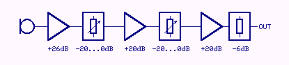
at its lowest gain, 20dB. For now let's ignore the noise of the gain blocks and pencil in 600R for the attenuators. For an input (mic) resistance of 150R, an ideal noiseless amplifier would hiss like 150R*10(20/10)=15k.
As drawn, the output of stage 1 hisses like 150R*10(26/10)=60k.
The first attenuator is set for 20dB, so after this attenuator the input contributes 60k/10(20/10) or 600R. Add to this the resistance of the attenuator (also 600R) and you get 1200R at the input of gain block 2.
Gain block 2 amplifies this by 20dB, so at its output we see 1200R*10(20/10)=120k worth of hiss.
Second attenuator is also set for 20dB and has a resistance of 600R, so at its output we see 1800R.
Third gain block amplifies this to 180k.
The third attenuator cuts this by 6dB for a final noise resistance of 45k, or a 4.8dB noise figure.
Now if the output attenuator is removed and its attenuation is moved to the second attenuator (now 26dB), the input of the second attenuator still sees 120k, reduces this by 26dB to 300R, add its own resistance to get 900R at the input of gain block 3.
Gain block 3 amplifies this by 20dB, to arrive at an output-referred noise resistance of 90k, or a 7.8dB noise figure.
On the other hand, if you keep the output attenuator and switch out the second attenuator and gain block for lower gain settings, the noise resistance is 30k, for a 3dB noise figure.
PRR said:I assume you are allergic to transformers.
Not at all, and what you suggest is intriguing, and definitely better than an input pad. I'll ponder this a bit more, and will go looking for appropriate iron.
As a matter of fact I would prefer a 2400:600 output transformer (plus some output load isolators) over a resistive 6dB output pad, but even a cheap specimen will cost a significant fraction of the BOM for the entire pre, especially if you factor in shipping.
JDB.
I believe you have not taken the noise current into account; you have considered only the thermal noise of source resistances. I don't know for which impedance you have optimised the bias of the input transistors. Supposing you have optimised the first stage for 150/200ohms and the subsequent for 600, the actual noise build-up will be ca. 3 dB higher, making the NF more like 7dB.
Anyway, a NF of 7dB for 20dB gain is not so bad. That will leave you with 102dB S/N; not bad...
The PGA2500 has a similar loss of performance and the THAT 1512 sees an increase of its NF of almost 15dB at 20dB gain compared to 60db, and it is recognised as a serious improvement in that respect over the 2017/2019.
Svart
Well-known member
The third attenuator cuts this by 6dB for a final noise resistance of 45k, or a 4.8dB noise figure.
Now if the output attenuator is removed and its attenuation is moved to the second attenuator (now 26dB), the input of the second attenuator still sees 120k, reduces this by 26dB to 300R, add its own resistance to get 900R at the input of gain block 3.
Gain block 3 amplifies this by 20dB, to arrive at an output-referred noise resistance of 90k, or a 7.8dB noise figure.
On the other hand, if you keep the output attenuator and switch out the second attenuator and gain block for lower gain settings, the noise resistance is 30k, for a 3dB noise figure.
Which is why I said:
That's a trick we use to fudge noise figure through gain blocks..
But I also read you wrong when I said that, I thought you said that you were putting the attenuator after the last stage, when you actually said after the second stage.
Svart
Well-known member
you know, I've always wanted to see what would happen if I used something like:
http://www.hittite.com/products/view.html/view/HMC580ST89
As a front end gain stage in a mic pre. I suppose a transformer is needed to match the front end and it would be much too high of a ratio to be practical. :-\
http://www.hittite.com/products/view.html/view/HMC580ST89
As a front end gain stage in a mic pre. I suppose a transformer is needed to match the front end and it would be much too high of a ratio to be practical. :-\
jdbakker
Well-known member
Svart said:you know, I've always wanted to see what would happen if I used something like:
http://www.hittite.com/products/view.html/view/HMC580ST89
As a front end gain stage in a mic pre. I suppose a transformer is needed to match the front end and it would be much too high of a ratio to be practical. :-\
...not to mention its 1/f noise corner.
JD 'probably measured in MHz' B.
Svart
Well-known member
For current or voltage? ;D
Honestly I can't find information on the current or voltage noise for these parts..
But I did find an interesting paper that claims to null out pink noise in a LNA.
Either way, I was going to suggest looking into some of the CMOS amplifier parts. They have low current noise and low voltage noise.
Honestly I can't find information on the current or voltage noise for these parts..
But I did find an interesting paper that claims to null out pink noise in a LNA.
Either way, I was going to suggest looking into some of the CMOS amplifier parts. They have low current noise and low voltage noise.
Similar threads
- Replies
- 11
- Views
- 6K
- Replies
- 19
- Views
- 2K
- Replies
- 42
- Views
- 8K