Dual 1176 Rev G and "vintage" 3U GSSL...w/pics!!!

GroupDIY Audio Forum

Help Support GroupDIY Audio Forum:

This site may earn a commission from merchant affiliate links, including eBay, Amazon, and others.

regularjohn

Well-known member
Joined
Jan 23, 2009
Messages
321
Location
Raleigh, NC
Two Rev G's sitting in a tree
L-I-N-K-I-N-G!  ;D
DualRevG.jpg


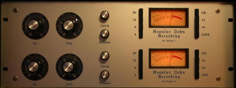
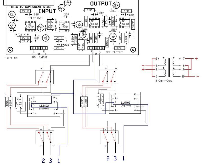
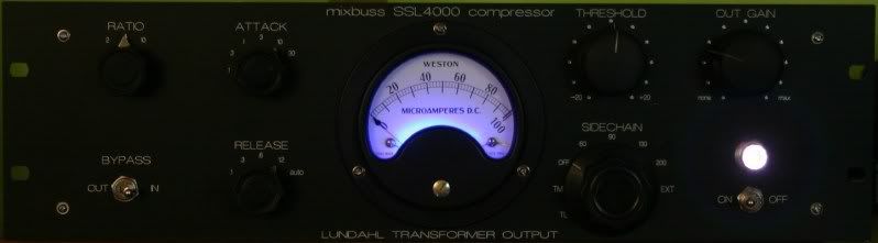
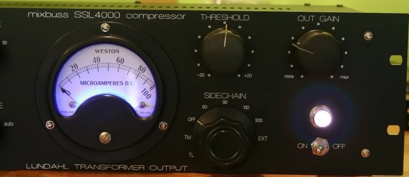
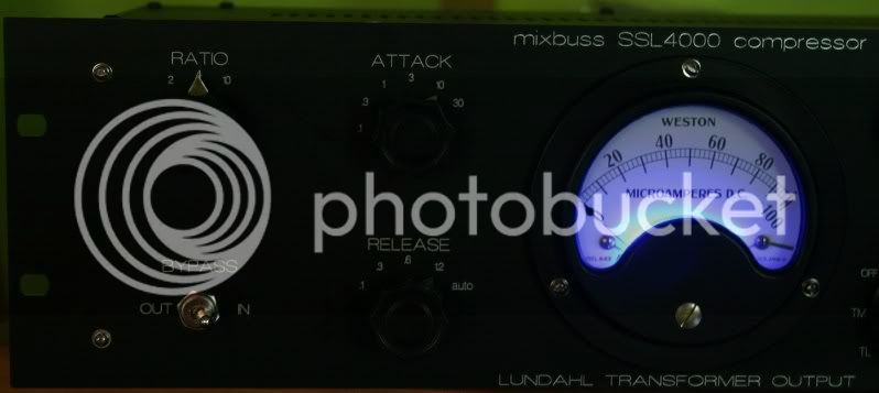
Here's my take on a Steffen-style SSL comp.  I added the blue LED to the vintage 4.5" Weston meter myself.  It's got a pair of Lundahl LL5402's on the output.  Vintage knobs complete the look!
I wired it up using the alternate connection scheme for the switches and pots that I came up with for the 22 channel gssl that I built.
VINTAGESSLFRONT.jpg

closelight2.jpg

closedark2.jpg

Inthedark.jpg

guts.jpg
 
I see you have 5402's on the output

could you share a little info on exactly how they are wired, resistor value changes etc?

I cant seem to get access to their spec sheet.

thanks
 
peat said:
I see you have 5402's on the output
could you share a little info on exactly how they are wired, resistor value changes etc?
I cant seem to get access to their spec sheet.
thanks
Sure, the 100R resistors on the GSSL output need to be changed to 22R.  The 5402's are 2+2:1+1 so to get the 1:1 output you need for the GSSL they need to be wired parallel primary and series secondary.
Here's the data sheet for the pinouts: http://www.lundahl.se/pdfs/datash/5402.pdf
Remember the data sheet is top view so the pin diagram is like you're looking down through the top of the trafo.

Thanks for the kind words guys!  :D
 
What, no turbo?

If youre going to use it on the mixbus, id seriously recommend it.


Other than that, looks absolutely frigging awesome! Great work!

/J
 
regularjohn said:
peat said:
I see you have 5402's on the output
could you share a little info on exactly how they are wired, resistor value changes etc?
I cant seem to get access to their spec sheet.
thanks
Sure, the 100R resistors on the GSSL output need to be changed to 22R.  The 5402's are 2+2:1+1 so to get the 1:1 output you need for the GSSL they need to be wired parallel primary and series secondary.
Here's the data sheet for the pinouts: http://www.lundahl.se/pdfs/datash/5402.pdf
Remember the data sheet is top view so the pin diagram is like you're looking down through the top of the trafo.

Thanks for the kind words guys!  :D

awesome, thanks alot
i couldnt seem to get to that link for some reason

ill be trying this out with my gssl's soon, still cant decide to go with lundahl or oep but
how do you like the sound of them
i was also thinking of putting a few relays to switch between transformer output and regular output
 
peat said:
ill be trying this out with my gssl's soon, still cant decide to go with lundahl or oep but
how do you like the sound of them
i was also thinking of putting a few relays to switch between transformer output and regular output

I think they sound great.  Definately different than transformerless.  If you search around, there's a thread here somewhere that has audio files comparing gssl's with lundahl, OEP, and transformerless outputs.
 
If you search around, there's a thread here somewhere that has audio files comparing gssl's with lundahl, OEP, and transformerless outputs.

Thanks just found it. And links still work!

http://www.groupdiy.com/index.php?topic=17886.0

The trafos definitely make it creamier. I think I'd personally want them on  a switch ideally though for when a clearer cleaner sound is desired. Nice with Lundahls.
 
have i got this right?

i guess it could be done with 4 DPDT relays all switching together?

LL5402GSSLMOD.jpg
 
The input on the 5402's needs to be parallel and the output series for 1:1.  Looks like you've got that reversed.
Remember the trafo is 2+2:1+1.  The way you've got it in your diagram is 4:1 , which will lower your output level.

1:1 wiring is:

On the input:
5 and 1 together = -
4 and 2 together = +

Output:
6 and 9 together
10 = -
7 = +

Look at the datasheet.  It's actuall got a diagram of parallel input/series output on it.
I also wouldn't take the trafo pin 3 to the XLR connectors because of the potential for ground loops.  Solder all XLR pin 1's to the same lug of an spst switch, and the other lug of the spst switch to chassis ground.  That way you can float the output if you need to.
 
ah of course, got mixed up the OEP thinking it was 1+1:2+2
makes sense now.

thanks alot for your help, ill be setting this up in a few months and will see how it goes!

would it make sense to put a similar switching system for pin 3 for connecting to an unbalanced source?
 
peat said:
would it make sense to put a similar switching system for pin 3 for connecting to an unbalanced source?

I don't think so, because I'm pretty sure that if you switch xlr pin 3 "off", or if it gets drained to ground by simply plugging in an unbalanced cable, you lose 6dB either way. 
Correct me if I'm wrong on that.
 

Latest posts

Back
Top