briomusic
Well-known member
Making a new topic for this as it doesn't fit quite in anywhere else, although a very similar question has been asked here:
http://www.groupdiy.com/index.php?topic=35947.0
Basically, I want to modify a spare SSL9k PSU board to provide me with single 24vdc for the EZ1290 as well as 48vdc for phantom power.
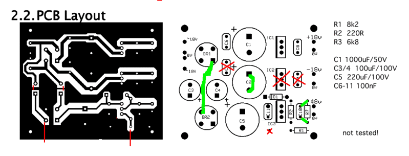
I have read the above thread with interest and also browsed the JLM forum, but I don't quite understand the JLM mod as it is only described on the pcb and not the schematic. I understand they are replacing one cap with a jumper to disable the negative rail and there is an additional jumper that connects "a" capacitor to "a" diode - but which?
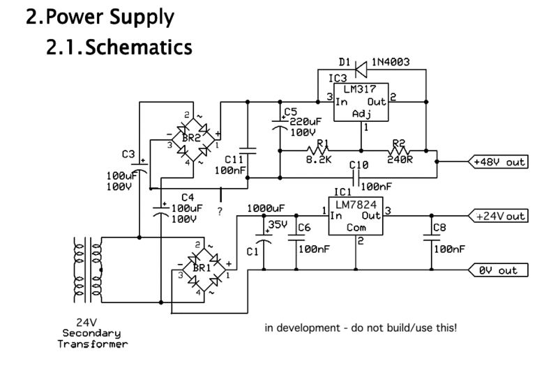
On the schematic below, I believe I managed to figure out the 'jumpered cap' bit in regards to the SSL9k psu, but I feel I am missing the second jumper, which I believe connects to the point marked "?". What node do I need to connect this to? Or am I barking up the wrong tree altogether?

(hope it is ok to borrow the ssl9k schematic...original schem is here:http://www.studio21.ch/diy/neeno/ssl9k/DIY_9k_Preamp.pdf)
http://www.groupdiy.com/index.php?topic=35947.0
Basically, I want to modify a spare SSL9k PSU board to provide me with single 24vdc for the EZ1290 as well as 48vdc for phantom power.
I have read the above thread with interest and also browsed the JLM forum, but I don't quite understand the JLM mod as it is only described on the pcb and not the schematic. I understand they are replacing one cap with a jumper to disable the negative rail and there is an additional jumper that connects "a" capacitor to "a" diode - but which?
On the schematic below, I believe I managed to figure out the 'jumpered cap' bit in regards to the SSL9k psu, but I feel I am missing the second jumper, which I believe connects to the point marked "?". What node do I need to connect this to? Or am I barking up the wrong tree altogether?

(hope it is ok to borrow the ssl9k schematic...original schem is here:http://www.studio21.ch/diy/neeno/ssl9k/DIY_9k_Preamp.pdf)


