Bo Hansen DI layout

GroupDIY Audio Forum

Help Support GroupDIY Audio Forum:

This site may earn a commission from merchant affiliate links, including eBay, Amazon, and others.
That'd be wonderful. As far as the pickups being used its the K&K Pure Mini (link)  http://www.kksound.com/puremini.html . Its a passive transducer pickup. Sounds wonderful might I add, but I need to be able to control the volume and would like to have simple control over the hi and lo frequencies as I find it more than beneficial in a live setting.

So Ideally I am thinking that a direct input box that took your active circuit, which i am adamant to use based on such wonderful feedback, and having a front end that had volume control and both hi and lo controls. I dont think mid will be necessary, nice, but not needed.

Is there any reading or schematics that I could refer to for inspiration?

I am hoping to build this within a months time as it is needed for a small tour coming up.

Thanks for such a quick response. I hope something can be built out of this dialogue.

-Brice
 
Brice,

I have received numerous inquiries on various modifications on my DI box in the most varied designs.

I have an idea that in the future to do a DIY thread to be called "have fun with the 1975 DI-box PC-card" and where I will try to make a lot of clever designs with this PC card and a small ad-on PC-card.
But of course, it's all about time, and I'm mostly busy with running my business, so it be when I get some free time.

When it comes to your desires, do you need more gain compare when you plug the acoustic guitar right into the original DI-box ?
What type of equalizer, a one knob treble or bass cut, or a one-knob tone balance/tilt, or two knobs normal treble & bass?

--Bo
 
Bo,

Thanks for your time! Truly. I think a one knob gain control with the ability to boost and cut would be best. And for eq I think a two knob setup would be best with simple treble and bass control.

I'm excited to learn through this project, have you any suggestions for reading and schematics to learn from.?

Thanks again,
Brice
 
I've been searching rather hard to come to a simple understanding of what circuit one would need to control and boost an acoustic guitar. I see plenty commercial products, but obviously their schematics are private and of no help. Does anyone know where I could start searching or simply a discrete circuit that'd rock this acoustic guitar ambition?

I appreciate any comments, especially productive ones

Brice
 
I just finished four DI's...  I got half way through before I came up with the idea of putting some Swedish colors on them!  They work great  but I didn't realize that I should only use red LED's...  How big a difference does this make?  I was thinking of putting a bypass switch on the LED's just to get a comparison between "with" and "without" the LED indicator. 

I find a subtle difference between them sonically, with the red and blue one sounding best to my ear.  Must be small differences in component values(?).  I just coupled these with an AML EZ1073 500 series kit preamp and got a GREAT sound tweaking the EQ on the mic pre...

Thanks!  Great, easy, and fun to build!


Attachments

  • s.JPG
    s.JPG
    80.1 KB · Views: 177
Hi "gzpz"

Nice color on your boxes, as a Swede I feel honored.

Because the LED's are connected in series with internal 24 volt feed to the DI-box electronics, it is good that the LED have so small voltage drop as possible.

Red LEDs have the smallest voltage drop compared to other LED colors.

Of course a few volts loss gives little difference for the DI-box headroom, but if we designers get to choose, we would rather choose some dB more headroom than a blue LED.

--Bo
 
I might try a different LED to tell if I hear a difference...

Yes, I'm from the USA, but my mother was Swedish and my godfather still lives in Gothenburg, now in his 80's, he was an electrical engineer, and is a wonderful guy.  I didn't have a good way to label the boxes but wanted to give you some honor for such a nice clean design!
Thanks again-
Dan
 
as you can see i had to do some routing to the board to make it work like that.

i just like my xlrs on the top to be able to plug and unplug my cabling with one hand by stomping on the box.
 

Attachments

  • IMG_0501.JPG
    IMG_0501.JPG
    141.4 KB · Views: 238
full props to bo hansen

who else is gonna show up?

frickin jeezus?

wth, over

king of direct, so give some respect  :D

should i see pat travers oct 7 at the el ray ,


or not?

can that old canadian still get it?

 
CJ said:
full props to bo hansen

who else is gonna show up?

frickin jeezus?

wth, over

king of direct, so give some respect  :D

should i see pat travers oct 7 at the el ray ,


or not?

can that old canadian still get it?
CJ, You mean the Fox Theatre in Redwood City,  If you show up on the 7th at the El Ray I think you will be dissapointed. ;)
 
Just finished my Bo H DI today -  and been playing Waves GTR 3 with it as a front end to my interface - great box !!

sounds really nice on Bass guitar too.

Thanks Bo - I know this is an old project now, but you have another very satisfied DIY'er here

great addition to my little project studio.

Cheers
PeteC
 
Hi!


I built four of these DI boxes with various transformers and i am really happy with all of them.


I am thinking about adding a variable hipass filter to my boxes, maby 20 - 400Hz. After a few nights of studying i am still unsure how to add this to the DI box...


Does anyone have experience with this or ideas on how to go about?


Kind regards,


E.
 
Edward,

There are two places in the circuit where you easy can make 6 dB per octave bass roll-off filter.

It is to reduce the 0.1 uF capacitor at the input, or reducing the 10 uF electrolytic on the output before the transformer.

With a switch may be choosing between a number of different values ​​of the capacitor.

As an example, the output capacitor can end up on the values 10 uF, 4.7 uF, 1 uF, 0.47 uF, but the best is to test out the value according to your own taste.
The bass roll-off may change slightly depending on the load Di-box is connected to, this is due to mirror impedance of the transformer.

If you do it with the input capacitor, will probably bass roll-off to become more constant, but the capacitor's value will be very small, due to the high input impedance of 1 Mohm.

There is another trick to get 12 dB per octave roll-off, adding another capacitor in series with the input capacitor, and between these connect a resistor that goes to the output on the last transistor.
Both of these capacitors must be changed in value for different roll-off frequencies

However, this circuit can probably affect the input impedance of the DI-box compared to the original design.

--Bo
 
I will start testing this by reducing the electrolytic capacitor on the output and see how it works out!

Thank you again Bo for helping out!


Kind regards,


Edward.
 
Hi again

I soldered a rotary switch with 5 positions choosing between 10uF, 4,6uF, 1uF, 0,33uF and 0,1uF as a first test. Then i fed pink noise into the DI box and had a spectrum analyzer to see what happens on the output. With the rotary switch at 10uF i had a completly flat response. Turning the rotary switch all the way to 0,1uF gave me a HPF somewhere around 60-70Hz acording to my analyzer.
I tried this with an electric guitar as well, and i thought the HPF was only and barely audible at its max position at 0,1uF. There was also a small pop when changing between the different settings on the rotary switch.

Now i am wondering what kind of capasitor i could use if i want to go smaller than 0,1uF to get my HPF to say 300-400Hz, and of course not affect the sound of the DI box?

Ideas?


/Edward
 
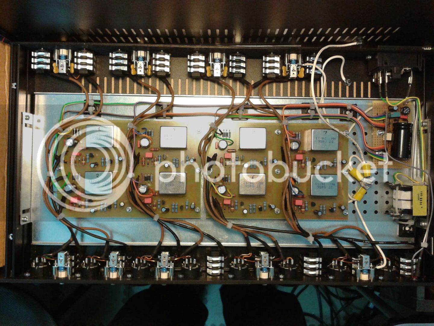
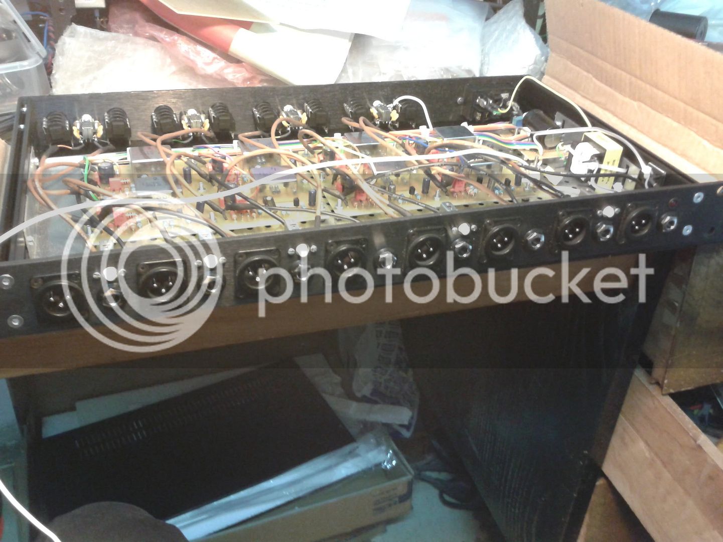
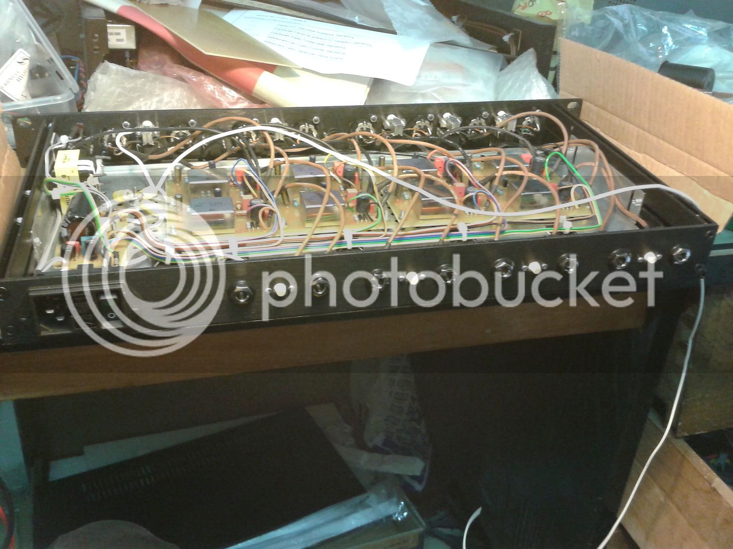
Hi everybody! let me show you my 1U rack 8 Bo's DI version  :)  they have an intrnal psu. Its for a band of a friend and they want a ground lift and a pad... I know that the groun lift is not required in that design but is easier and they are more relaxed with it  than try to explain to tem why its not necessary..  :p  I  put in them the haufe transformer.
Thanks Bo Hansen for that very nice ciruit and all who have made this design possible!!

Sorry for the big pics...

BOHansen8DIinside.jpg


BoHansen8DIfront.jpg


BoHansen8DIback.jpg
 
Edward,

Simply change the capacitor that drive the output transformer primary, may be a rather uncontrolled and smooth slope.

With just a capacitor in series (passively coupled) becomes only a slope of 6 dB / octave, and if you have varying load from time to time on the DI-box XLR output, this will make the bass cut filter does not become constant.

Let me come back with a smarter solution to this problem, so I can save a lot of experimentation for you.

Maybe I have a some spare time between Christmas and New Year to take a look at this.

--Bo
 
Just built a couple of these and they are awesome. Thanks to those who made it possible.

A quick question: Does the "amp out" pass through the transformer. Logically I don't see why it would but I'm pretty certain that I hear a "thickening" of the tone. Placebo ?

Thanks
Peter
 
Back
Top