Bo Hansen DI layout

GroupDIY Audio Forum

Help Support GroupDIY Audio Forum:

This site may earn a commission from merchant affiliate links, including eBay, Amazon, and others.
Somorastik,

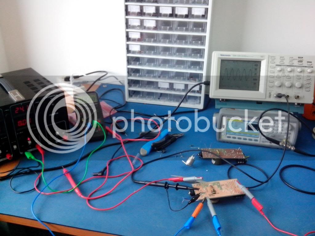
If the DI-box electronics is working ok, it shall only draw 3,5 ma from 24 volt supply.
So I think you have some problem with your construction.

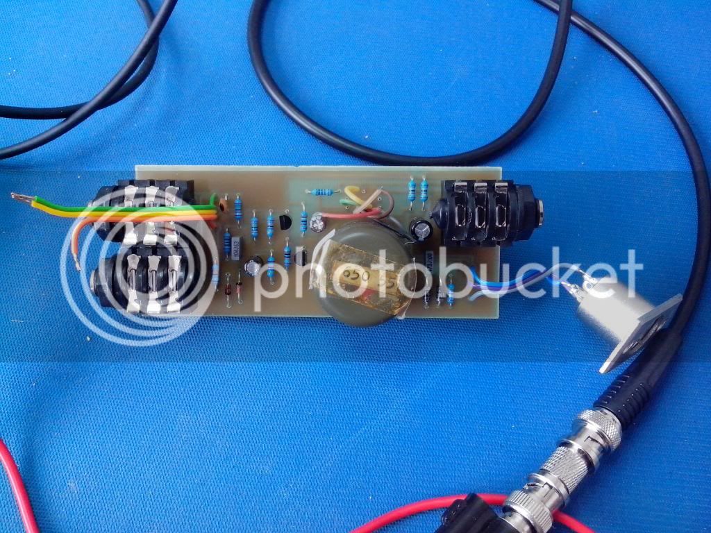
If you not feed the voltage supply from phantom power, you shall connect a regulated 24 v dc voltage in this point there the two 6,8 k resistors is connected together.
(dissconnect the two resistors if you not use phantom power)

--Bo
 
So,

I tested my DIs (two in the same box) and I am getting SOME noise, not noticeable unless I really crank the gain. It is quite obviously more noisy when I used electric guitars.

Acoustic guitar plugged directly into the box, and then the box is connected directly to my recording interface (Scarlett 18i20). I did this with a guitar amp connected to the amp output... Not noisy, but a faint little bit. You start to hear it clearly once the gain is pegged, but that's the case with everything.

Electric guitar connected the same way was definitely noisier.

I'll be getting my hands on a keyboard sometime in the next week to get the guitar pickups out of the signal chain =}
 
Jasonallenh,

Can I see a picture from the DI-box inside.

Do you have clean phantom powering from your sound card ?
(have you try with a other pre amp)

Maybee you use a noisy brand/type of transistors.

If you not have anything plugged on the DI-box input, and the jack is shorted to ground, do you still have noise/buzz ?

--Bo
 
Bo Hansen said:
If you not have anything plugged on the DI-box input, and the jack is shorted to ground, do you still have noise/buzz ?

--Bo

It is absolutely silent when nothing is connected to the input jack. I think I may have corrected my problem. I plan to test it with the test tone on my cable tester. I feel like that will tell me if it is a grounding issue once and for all. (Don't know why I didn't think of this before  ;D).

PICTURES PICTURES PICTURES! I keep forgetting to do that, so sorry.
 
Bo, thank you so much for the reply. You are the best. I managed to get the DI working great. As you noted REMOVE the 6k8 resistors when testing with an external supply!!! I guess when one does not do this the core gets saturated and the current drain raises since the transistors need to work in a different operating point?

Anyway here are the photos. My board contains the heart and soul- the Bo Hansed DI, a throughput jack and an attenuator switch for 0, -10 dB, -20 dB. I am using an old TESLA transformer 5AN650 55.

8)

Thanks Bo!

2014-03-18121122.jpg

2014-03-18121110.jpg
 
I am so exciting to start making a DI by my own. I pick the OEP transformer but I found there is a metal enclosure which is sold separately. Is this metal cast necessary?

Thanks!

OEP A262A3E  AUDIO FREQUENCY TRANSFORMER
1689033-40.jpg


OEP A262CAN  TRANSFORMER ENCLOSURE
42416187.jpg

 
Thanks Mr. Hansen,

How can I test the unit before I plug it in the mixer so I won't blow up the would system?

Again, thanks for your great work!

Regards,
Steve
 
Not very much can go wrong... (Even if the circuit would be a complete short circuit, the maximum load would be 2 x 6.8 K resistors, causing a current of 3.5 mA in each 'leg'!)
What you could do, is leave the two 6.8 K resistors out of the circuit and connect a 24 V. power supply to the 100 uF capacitor.
If you don't get smoke, you can safely connect the secundary side of the transformer to a mixer and see if you get an audio signal.
Since the DI box is now externally powered, it does not draw any current from the mixer input.
If everything passes this test, add the two 6.8 K. resistors and you are done!
 
I have just finished the DI but don't seem to be able to get any sound at all when I tested it.  I have done the 12 and 24 volts tests and everything seems to be fine as well as the 36 volts test for the xlr socket and no problems there also.  The transistors also seem fine and connections to the input jack seem to have a good connection.  Does anyone have any ideas or know any other tests that I can try to get to the bottom of the problem?
Thanks
 
alec1511900,

If you have 24 v over the 100 uF electrolytic and also approx. 12 volt om the both transistors emitters, the electronic must be in function and work ok.

Maybe you have problem with the output transformer connections ?

Try to check this:
Conect the DI-box to a phantom powered mike-input as normal, and connect the unbalanced telejack output to a guitar amp input.
If you have sound in this case, it is some wrong with the transformer.

--Bo
 
Thanks for the reply Bo, I thought it could be the transformer so thanks for the confirmation.  I'll do some more tests when I get a chance.
 
Hey there Bo! Thanks a lot for your contribution by making the DI schematic public, it sounds great even with a Vigortronix transformer, for both guitar and bass.

As a way of apology to a friend (I dropped his guitar, scratching it up pretty bad  :-[ ), I am building him a load box (30 ohm 200W, made from 4x 30 ohm 50W resistors in series parallel) and the DI in one enclosure. I've prototyped the circuit without a chassis, it sounds excellent - with the amp driven all the way up for maximum saturation and an impulse response thrown on top of it. great for silent recording.

now that i'm looking at different ways of housing the circuit, I'm a bit confused as to how I should go about it - although it was primarily meant to be a simple load box with an output, i figured it would be better to throw a balanced output with the ground lifted, just in case of any voltage problems between amp and interface.

my problem: i'm just a little confused about how the grounds between the two circuits should work. i drew up the following circuit - does this look OK? all the jacks are isolated from the chassis using plastic washers. i'd be really grateful if somebody could verify the correctness of this circuit, or tell me if there are any foreseeable problems. thank you and best regards from bombay!
 

Attachments

  • DI-Loadbox.jpg
    DI-Loadbox.jpg
    269.1 KB · Views: 64
flood,

You can of course combine the ground systems for both the dummy load circuit and the DI box electronics and place my ground loop suppressor in another place.

But I will not confuse it for you and other readers who may be interested in a similar idea, I suggest that the ground system is divided into two units.

The best way is to let the dummy load circuit belong to the guitar/bass amp ground systems, and the DI box chassis ground belong to the mixing consle ground system,
the same ground system idea that DI box has in the original, so it can isolate mains connected devices that are connected to the DI-box input or un-balanced output from the mixing console or preamp ground system.

--Bo

 
Bo Hansen said:
The best way is to let the dummy load circuit belong to the guitar/bass amp ground systems, and the DI box chassis ground belong to the mixing consle ground system,
the same ground system idea that DI box has in the original, so it can isolate mains connected devices that are connected to the DI-box input or un-balanced output from the mixing console or preamp ground system.

--Bo

Thank you for your quick reply Bo! Just to make sure I understand your instructions correctly:

1. The chassis is connected using a screw lug from the chassis to Pin 1 of the XLR jack. (I'll call this one GND1)
2. The ground loop suppressor circuit is connected at one end to Pin 1 (GND1) and at the other end to the DI box circuit ground (GND2).
3. This would mean that GND2 will have to share the same ground as the load box when the two are connected, and my drawing is ok?

I'm just concerned about preventing any accidental damage to his sound card or amplifier - both are quite expensive. Of course, I will be testing it extensively on my own setup before giving it to him. I also just realized that I did not show the DI circuit as being connected to circuit ground in my drawing, apologies for that.

Thank you and best regards!
 
flood,

Yes, your description is right.

Use a separate metal box to contain DI box electronics the same way as normal.
Install the dummy load components separately outside DI box electronics.
It is important to not use the DI box the chassis as dummy load ground connection.

Mixing console, preamp or soundcard is protected from short circuit or other fault, as long as the transformer balanced output is used, and the XLR pin 1 is ground and nothing else.

--Bo
 
Awesome thread here!

So I am a total noob with DIY projects and am using this awesome DI as my starting point. I feel pretty confident moving forward for putting it together, but ran into one question that is super basic but something I was curious about. I got my Hansen DI PCB from PCB grinder.com and have been following their instructions, and there isn't anything detailing the wiring step, just a photo. While researching Bo Hansen's website about grounding it says "[it] shall only be grounded on the XLR output connector pin 1, and also connected to a solder tag fixed in one of the XLR fasten screws." The photo on PCB grinders assembly instructions (though low resolution) clearly shows the ground terminal wired to the chassis, as opposed to the instructions on Bo's site. Is this PCB different in any way from the original design? Has anyone else acquired their PCB from PCB grinder, and if so what was their grounding wiring like? Any information would be hugely helpful so I can start this build. Thanks!!!!

Glenn
 
Hey guys, I'm working on a smallllll PCB to use when a transformer must be wired off the board, as is the case with my jensen jt-13k6-c. It saves you quite a bit of space as it's only about 1.5" x 2.5"

https://www.dropbox.com/s/r93oktrj62eb9bj/BHDI%20Rough%20Draft.jpg?dl=0

Does this look correct? I've left six pads to use in the center for transformer connections. 

Thanks for your patience!  ;D
 
Glenn,

I myself have been involved with the development of this PC-layout, and therefore know that it is correct.

The grounding is simple, just follow the text on the PC board connectors. XLR pin 1 to pin 1 and chassis to the metal case, a proper screw, such as the one screw that holds the XLR connector.

Look at the photos here on the forum, there are lots of clear photos of peoples builds that are properly made, and questions and answers about the grounding in plenty through the years.

Good luck with your DIY.

--Bo

 
Hi All,

I originally posted this in the main BHDI thread, but I figure it should land  here.

I designed a PCB for use with non-standard transformers that HAVE to be wired off the board (Jensen Trafo for example).  It's as small as possible (about 2.5" x1.5") and allows for you to fit the whole DI in a BB sized stomp-box.  I'd like some advice on any improvements/suggestions that anyone may have.

The basic design is here-

https://www.dropbox.com/s/r93oktrj62eb9bj/BHDI%20Rough%20Draft.jpg?dl=0

There are six pads to the immediate right of the BC550C where you would connect your transformer. Remember: the pads aren't meant to accommodate a PCB-mount transformer! This means you must find a way to isolate the transformer case from your enclosure.

What do you guys think!?
 
Back
Top