http://www.freeinfosociety.com/electronics/schemview.php?id=986
http://www.audiosharing.com/archive/western/we_amp/we_amp.htm (1126A Is last PDF in Amp sectio)
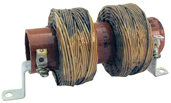
Was looking at these schematics thinking of DIYing for fun & am wondering about L1 coil/ coils in the 1126A schematic .......what are they ? what do they do ? on so on ....prob hard to DIY ?
The 1126 (first link) doesnt seem to have L1 coil or whatever.....why ? I take it the L1 is a later addition and is an improvement ?
The 1126 is hand drawn Im wondering if the drawer has shown coils as resistors ?
also worries me a little that the 1126 hand drawn is all correct if Im gonna DIY you see.....
One more question, why are there .03 MFD & .02 MFD capacitors wired in parallel connecting the 1st & second stages ?..........Ive seen in other circuits where Im told smaller caps pass round higher frequencies or something ?
Thanks for reading & any responses ...Happy New Year
http://www.audiosharing.com/archive/western/we_amp/we_amp.htm (1126A Is last PDF in Amp sectio)
Was looking at these schematics thinking of DIYing for fun & am wondering about L1 coil/ coils in the 1126A schematic .......what are they ? what do they do ? on so on ....prob hard to DIY ?
The 1126 (first link) doesnt seem to have L1 coil or whatever.....why ? I take it the L1 is a later addition and is an improvement ?
The 1126 is hand drawn Im wondering if the drawer has shown coils as resistors ?
also worries me a little that the 1126 hand drawn is all correct if Im gonna DIY you see.....
One more question, why are there .03 MFD & .02 MFD capacitors wired in parallel connecting the 1st & second stages ?..........Ive seen in other circuits where Im told smaller caps pass round higher frequencies or something ?
Thanks for reading & any responses ...Happy New Year