Multi heater circuits - re "Valve amplifiers" by Morgan Jones

GroupDIY Audio Forum

Help Support GroupDIY Audio Forum:

This site may earn a commission from merchant affiliate links, including eBay, Amazon, and others.

mikeyB

Well-known member
Joined
Apr 12, 2005
Messages
569
Location
Manchester UK
Couple of things - first off - got a copy of "Valve amplifiers" by Morgan Jones - looks to be some good stuff in there if you want to learn about design.
Are there any other good books like this aimed at the beginner/novice to get into the design aspect?

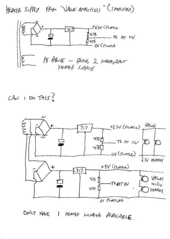
Section on psu that shows a twin regulated heater psu - outputs are floating but each section has it's own secondary winding. Further reading suggests that you treat the heater wiring as you would for ac - ie twisted pair with the output centred to 0V with 2 47R close tolerance resistors (humdinger is the old term is it?)
ie. you end up with +/- 3.15V on a 6.3V supply.

Is it possible to connect 2 bridge rectifiers to the one ac winding - then one set of +/- feeds say a 9V regulator that can be referenced +/- 4.5V and the other set of +/- bridge outputs feeding a 6.3V reg that can be referenced +/- 3.15V; reason being I want to use valves with 9V and 6.3V heaters? - purpose being to only use 1 secondary instead of 2 secondaries for the heaters.

Thanks in Advance :)

 
...and another question.

Is it possible to series connect heaters of valves without cross talk issues - ie. 2 valves with heaters series connected - say 2x 4.5V heaters across a 9V supply - each valve being in each channel of a 2 channel/stereo unit?
:)
 
Sounds complicated. Maybe I can't understand from text? A picture sure would help.

Separate heater circuits are usually about some heaters at +2VDC and some (cathode followers) sitting up at +200V. If both are on the same circuit, heater-cathode insulation is stressed, could break-down.

You can run 6V heaters on a simple 9V supply with a resistor. Total heat is the same as dropping the same raw voltage to the same final voltage.

If you have multiple heaters at similar current, and "need DC heat", it often makes sense to wire them in series from like 27VDC.
 
Indeed what PRR mentions is true and it is also especially true for Cascode gain stages where two tubes sit on top of each other (cathode of tube on top connects to plate of the bottom tube).  The heater for the top tube needs to float to avoid arcing over with heater-cathode voltage rating specified in the tube datasheet as PRR mentions as well..  The cathode of the top tube is sitting at the HT high voltage of the plate of the bottom tube in this instance...

Also Bruce Rozenblit's book is a simpler book available from Audio Amateur (AudioXpress.com also called Old Colony Sound Lab) in Peterborough New Hampshire (next town over from me just over the "mountain" ;-)

http://www.audioxpress.com/bksprods/BKSTUBDES.htm

I have both the book you mention and Bruce Rozenblit's book too... both are great...  Rozenblit's book has some simple algebra that can easily substitute the numbers for your design...

Cheers,
-chris
 
PRR said:
Sounds complicated. Maybe I can't understand from text? A picture sure would help.

Here's a quick scribble of what i'm trying to acheive. Simplified it - left out all the reg components just to keep it clear as possible. Here goes....
heaterscan.jpg


ps regarding series connected pair of heaters - one valve in channel 1 and the other in channel 2 - am i going to have cross-talk problems - is this scheme possible?
 
It won't float as expected. The rectifiers and first caps will give identical potential. Therefore your "CT" can't be the same downstream of the 9V and 6V regulators.

Make 9V. Run your 4.5V from that. Say your 6V heater is 0.3A. You need to lose 3V (2.7V). 3V at 0.3A is 10 ohms. Split that, two 5 ohms, one in each end, so the heater is in the middle. (Two 4.5 ohm if you want to be fussy.)
 
Thanks PRR - i thought the common bridge might be the stumbling block! So is it ok to have the tubes of 2 different channels in the same series heater chain? I suppose it's just the same as 2 channels sharing a common parallel connected heater supply?

Thanks for your advice

I mentioned in another post
http://www.groupdiy.com/index.php?topic=37276.0
about imbalance in the control circuit tube diodes resulting in control voltage ripple - is it possible to put a cathode trim pot like the cathode trim in a differential stage?
 
Back
Top