PM1000 Direct out idea. Can someone double check this please

GroupDIY Audio Forum

Help Support GroupDIY Audio Forum:

This site may earn a commission from merchant affiliate links, including eBay, Amazon, and others.
T

tubejay

Guest
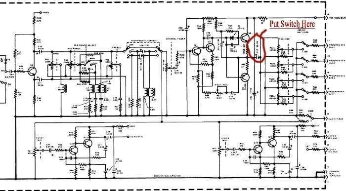
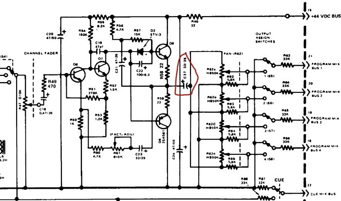
I was bouncing a direct out scheme off of Josh Karnes who has the wonderful PM1000 page on the Krash Jones site. He came up with the idea of putting in a switch after C37 to give me a switch that would either send the signal to my output transformer or on to the buss matrix. I want direct outs, but I also want to retain my buss outs. I don't need to ever use both at the same time, as I don't use this for mixing, only for tracking. However, I still need to buss snares and guitars together. I wanted to do this without deviating from the original design too far.

Josh's thoughts (mainly his) and my own were that using a PM1000 600:600 output transformer after C37, coupled with a switch to separate the mix buss from the direct out so that it's either going to the direct out transformer, or the buss matrix, shouldn't screw anything up, and stay close to the original design.

So here's the two parts to the input module schematic:

PM1000InputModuleSchematicpart1.jpg


PM1000InputModuleSchematic2.jpg


Closeupofoutputarea.jpg


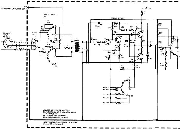
For a better look, here's the original schematic...warning this file is 3.4MB:

http://home.new.rr.com/lordjimbo/PM1000E_2.pdf


Can anyone recommend a switch that would be good for this??
 
Yes, that should work.

But you may want to make C37 somewhat larger, say 100uF.

And I think you'd need a second part of the switch that shorts the now-open inputs of bus to ground, in order to preserve constant bus impedance..

Any dual-pole-dual-throw switch should work - why not use the type that's already used in the desk?

Jakob E.
 
Why do you even need a switch? Just tap the wire that runs across the Pan pots to a jack. If you don't want signal on the bus, use the Assign switches.
 
Thanks Jacob! I'd take some switches from the console, but there aren't any to take. I'm keeping the whole thing in tact except maybe the echo/aux sends, which I won't use. I'm thinking of removing the Echo 2 pot. I'll probably leave it hanging inside the module and connected to the circuit still, and tape it off with electrical tape (so as not to cause other problems) but will remove it from the panel to make room for the direct switch.

I kind of looked around over at Mouser and Digikey and couldn't wade through it all. I'm looking for something pretty cheap. I need an on-on switch, correct? It also has to be panel mount.

Anybody of have a cheap source of DPDT panel mount, on-on switches that are pretty small? I need 10 of them.

Here's the space I'm working with for the Aux 2 area.

panelcloseup1.jpg


Panelcloseup2.jpg
 
[quote author="PRR"]Why do you even need a switch? Just tap the wire that runs across the Pan pots to a jack. If you don't want signal on the bus, use the Assign switches.[/quote]

The worry was that if I did it that way and ran from the pan area to a transformer as a direct out, then when I assigned something to the bus, that there might be weird impedance issues, and level problems driving both the bus and the output transformer. Is that wrong?

My original thought on this was that I would cut the trace from bus 4 and redirect it to the output transformer. That way when the bus 4 button was pushed it would go ONLY to the output transformer, and when not pressed it would completely disconnect the output transformer. That way I would be without one bus on those modules that I wired up this way. Josh and I were concerned that this might change the circuit and cause problems. I guess if the trace to buss four is grounded, I'm not sure if it would. I don't really need 4 buses on these modules as I'll still have 6 modules that are original with no direct out that are still connected to bus 4, so this would be perfectly acceptable if it's not going to screw up the sound/impedance or anything like that. Then I won't have to spend a bunch of money on switches either.

Thanks,

Jay
 
The right side of C37 is a very low-Z output with only 2.5K loading. It can drive an added 600Ω transformer fine. Only thing I might do is change C37 to maybe 100uFd and add about 100Ω in series with the transformer.
 
Josh here...

FWIW I'm driving the tranny right from C37 with no added R and no increase in C37 value. No low end problem, no need (imho) to replace C37. But it's not a bad idea, esp. if the board needs a re-cap anyway. The bigger cap certainly won't hurt anything.
 
Thank you PRR and Krash! I'll try it without the 100ohm resistor first and see how it goes. Once I test it I'll post back here.

So at this point I'm just going to leave everything alone, attach the 600:600 transformer after C37. I won't be using the buss outs on these channels 99% of the time anyway. I plan to leave 6 channels without direct outs, that I only use for things that need to be bussed. That should cover me 99% of the time. It appears to me that when there is nothing assigned using the buss switches that it's not connected in any way other than ground to the busses. So it should be cool...

Now I just need to figure out how to mount the transformers and how to keep it all modular...
 
Okay, I just finished the first module direct out. Well, not finished, but the transformer is wired into the module now.

Here's what I finally (after extreme hemming and hawing) decided to do. I kept it really simple. I went straight from C37 into the transformer.

I then connected the output of the transformer to the connector. As Krash Jones pointed out to me, the pins on the connector are REALLY fragile. You can't keep the iron on it for longer than a couple seconds or it will melt out. With that advice in mind, I was able to connect the two output transformer connections to that connector with little trouble. The good news is that if you screw up, there are about 10 other open pins available to try on.

EDIT: I HAD TO CHANGE THIS. If you have a PM1000 console, and are mounting it in the console, you can not do it this way. The PCB that the female side of the connectors mounts to inside the console ties both sides of the connectors together. So I'm adding a little 3pin connector. There's enough room for a wire to go under the spot where the lid of the console comes down on the modules. You won't be able to see it when the lid is shut.

If you are RACKING your modules OUTSIDE of the console, then you can still solder to the other side of the edge connectors without any issues.


So, here's the final output transformer pin out (using the original 1:1 PM1000 output transformers). This is the first I know of this being printed on the lab.

Brown gets connected to the negative side of C37
Red goes to ground
Blue goes to the hot connection on the XLR
Green goes to the negative connection on the XLR

That's it. Here's some pictures:

The first pic is the raw output transformer. Note the two screws coming out of the bottom. They provide a really easy way to connect the transformer to the frame of the module. If you put them into the cup of the frame, and then simply wrap electrical tape around the transformer REALLY TIGHTLY, it actually stays in there very securely. Plus, it takes about 1 minute to mount the transformer to the frame this way, which is good for folks like me who despise metal work.

Rawoutputxformer.jpg


Next up is a picture of how it looks mounted.


Next up is a picture of the wiring to the PCB. I connected the ground wire as close to the negative side of C37 as possible. Don't ask me if this was wise or a good idea, I don't know. I twisted them together up to that point, that was my reasoning and thinking behind doing it this way. It's hard to see the black wire, but it ends up pretty close to -c37.

Wiring.jpg


Finally, here's a picture of me holding up the original coupling cap next to the new film coupling cap. I REALLY went overboard, without realizing just how big a 3.9uf film cap would be. It BARELY fit on there, and I obviously had to solder on extended leads to make it fit. I used a little electrical tape here as well to hold it in place, though the picture doesn't show it. It's odd because the schematic calls for a .47uf cap. On all of my modules, Yamaha had 1uf tantalums in there. So I wanted to go crazy on this cap and make it pretty large in value. I had no idea the cap would be 1" by 3/4" by 1/2". This is a really frickin' big cap. Heck, it's almost as big as the input transformer. It's actually bigger than the OEP transformers I used on my G1176.

inputcap.jpg


Anybody think I'm screwing $hit up here?
 
Hmm, it looks like one of my pictures got through Ethans resize filter. Sorry about that guys!
 
> one of my pictures got through Ethans resize filter. Sorry about that guys!

Yeah.

And even "re-sized", our browsers have to download the WHOLE picture.
The "resize" just forces the display size,
not the fact that you just posted about
a third of a megabyte of pix
for all of us to download.

And even if you don't care about our smoking modems,
some hosting service quotas will lock-out after
a hundred folks hit the thread.

Give us a small re-sized taste, and link to the rest.
Let each viewer decide if your porn is worth getting.
 
Hello!!! This is my first post here! I am also trying to wire direct outs on a pm1000.

After looking at your new post that shows how you wired direct outs, I cannot tell what is going on with the ground (red) wire, and the (brown) wire that goes to c37. Could you take an above view so I can see where the C37 tap wire goes to exactly and where the red wire is grounded at. I just cant figure out where you grounded the transformer. Also, the input cap you changed to a big film cap. Is this only to make it sound better? Also I cannot tell from the photos exactly what is happening am in trying to do what you did!!

Also do you or anybodyelse possibly have any extra pm1000 output transformers to sell or know where to get any? Thanks..I would love to be able to finish all this stuff!! I am pulling the two transformers out of the echo sends to try this now!!

Todd Seibel
aka "iflyinmymind"
 
Hey Todd, welcome to the lab! It's good to get some more PM1000 modders and owners around here!!

If you look really closely, you can see where the wires are going. The black wire is hot. That connects to the point in the picture, or you can connect it to point B0 labeled on the PCB. They both connect to the negative side of C37.

As for the red ground wire, you can connect that to ANY part of the ground plane, which you can see as the line going all the way down the right side of the PCB, and then it cuts through middle where my wires are connected. Let me know if that helps. I tried getting a clearer picture, but my camera said, "forget you chump, I won't do this any clearer!".

Yes I did change the big input cap to a film. I haven't been able to do any listening tests yet. I'll report back on that. All of the EQ caps I switched to MKP caps. The other tantalums, I switched to MKP's as well. I switched that input to a MKT, because the MKP of that size was like $6 a piece. I'll probably still pick up a couple MKP's of that size (3.9uf) and check them out for the hell of it. I did all Panasonic FC's for the rest.

In a previous post I mentioned that the input cap on schematic was listed as .47uf, but that Yamaha had installed 1uf in all of my modules. I spoke too soon. They installed 1uf in a few of my modules. In the rest of the modules they had installed 3 or 3.1uf caps (can't remember off the top of my head) which I thought was weird. That's why I went with 3.9uf films. I wanted to go a little bigger than the max stock they had, and I certainly didn't want to go less than the max value I'd seen in there.

How odd that they would use different values on different modules within the same console. They also used different brand electros and tantalums between strips as well. I'm assuming that I have an all orginal console too, because the numbers all match up nicely, and it's about half and half one type/one value.

Sorry again PRR, I didn't realize that you still had to download all of the pictures full size. I thought it was automatically shrinking the download down for you. I'll be more mindful of that in the future. I can't tell, I've got cable and everything just comes up within a blink of the eye. Once you go broadband...you never go back!!! It's bliss... :guinness:
 
Okay!!! Thanks for the clarification. It helped!! I adjusted the mid tones in photoshop and am able to see exactly where you connected the brown wire (Neg. side of C37). I also recognize the ground plane, as to solder the red (ground wire from transformer).

I guess you abandoned the ,switch in the echo pot, I actully think it could be cool to put the TRS connector where the echo 1 pot is. I think it would be possible depending on the depth and connector.

I am just wondering if it would be easier that way instead of wiring it like krash joses did, where the outputs are all on the back of the mixer. I am just wondering about the ground connection to the TRS connector.

I guess you have to have one..right? Sorry newbie question i know.

Would you first ground the transformer to the ground plane, and then run another ground wire to the output connector from the same point the transfomer is grounded at on the ground plane.

Is that what I would have to do to gound the connector and output transformer I just installed, correctly?

I am hoping to be able to use the board to mix certain channels of stems from my daw. So when I am done tracking, I could connect the daw outputs into the mixers inputs.

It seems as though I will still be able to assign all of the inputs to the output busses or use the direct outs by assigning nothing to the output busses.

Okay...well I am off to steal the echo send transformers and start my two experimental channel strips.

Thanks for all the help!!!

Todd
 
Hey...Tubejay!

I am wondering if after you did your mod...the preamp direct out can be used and ,during mixdown, you can then still assign the channel to the mix bus and not have any noiose or grounding issues?

Thanks,

Todd
 
Hey Todd,

Sorry for the delayed response! I had a monster session to contend with the past couple days. Unfortunately I was unable to test my direct out scheme yet. My console and my studio are a half hour from my house. I do all of my DIY stuff at my house, and have to wait until I'm at the studio to test it.

I thought that the connectors on the back of modules were two independent strips of connections. When the modules are out, there's no connection between the two strips. However, when I got to the studio and looked at the PCB that holds the female connectors, I saw that both sides were tied together via the PCB.

Bummer, so now I have to buy some little 3pin connectors to finish the job up. Good thing I only wired two of them up. So I won't be able to report on the sound for a little bit longer. I'm going to have to wait for the 3 pin connectors to come in.

To answer you question though, I'm thinking that the answer will be yes. I think that the way I've wired it will allow me to use the buss outs and direct outs at the same time. I made C37 a 150uf cap, and beefed up all of the caps in the amplifiers on the modules...and I'm hoping I'll have enough juice to do both. I'm not wiring 6 of the modules with direct outs, so I'll still have enough room on the console for bussing a few things for recording. I won't be using my PM1000 for mixing...at least that's what I'm thinking at this point.

So yes, I didn't go with the switch in the echo pot. It seemed to not be needed, and it would have been a real bitch to get installed on the front panel, given the design of the modules.

For the outputs, I actually want them on the back of the console. You could do it any way that works, but for me it's just easier to have them at the back of the console with everything else. The only difference between crash's design and mine is that he mounted his transformers in the back of his console, and I mounted mine in the modules. This was just easier for me, given that I have to work on my modules at home.

For grounding the outputs, I'm not sure what I'm going to do yet. I'm hoping it won't matter. For now, my plan is to tie all of the ground wires on all of the connectors together. Like this:

O-O-O-O-O

And just daisy chain them. Then I'll ground them all at the same point. I'll see if there's a common spot that everything seems grounded in the console. If not, then I'll just try connecting the ground wires to different places for the lowest noise hum. I suspect it won't matter where I ground it though. I don't think it's going to make a difference. There's no hum anywhere in my console, and it doesn't seem to be star grounded.

What transformers do the echo sends use?

Let me know if I missed any of your questions, or misunderstood any of them.

Thank,

Jay
 
Back
Top