Console signal flow, input cards, general discussion on API styled DIY mixer

GroupDIY Audio Forum

Help Support GroupDIY Audio Forum:

This site may earn a commission from merchant affiliate links, including eBay, Amazon, and others.
I don't know the correct answer but I would hope they would be different. I use 3 separate grounds in my builds:

DGND - "dirty" ground for high current or noisy stuff like LEDs, relays and digital signals
AGND - "audio" ground for quiet stuff although I use it very sparingly (for inputs sections)
PGND - "power" ground for not just power supply bypass but everything else that is not DGND or AGND

These grounds all are completely separate until they get back to the ground plane of the power supply where they all connect along with earth ground and everything else ground-ish.

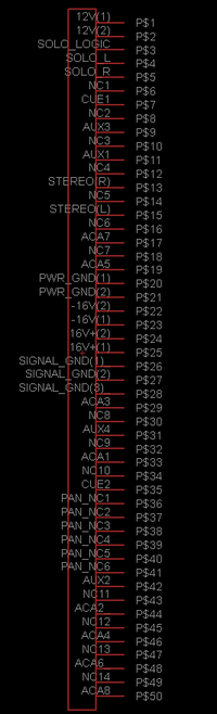
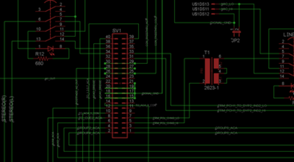
I would be slightly surprised if API did not do something vaguely similar but that's not exactly what I see in your schematic because "AUDIO COM BUS" sure sounds like it's just for audio but the "COM" on the input is used for the high gain mic pre and bypassing power so that is not consistent with my above described method.

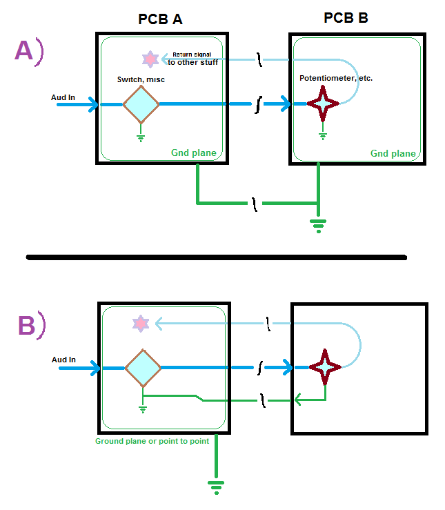
Having said that, the folks here will say that star grounding is not as important as carefully considering where currents are flowing and laying out traces / running wires so that the return current closely parallels it's source (meaning traces / wires should be physically close so that magnetic fields cancel each other).

Personally I feel like these are two different equally important concepts: star grounding is about minimizing ground noise pollution whereas making return currents closely parallel source currents is more about minimizing EMI from radiating around inside.
 
L´Andratté said:
One thing: can you explain in how far is EMI a problem with audio ground/0V reference ?
I'm not sure I understand the question. If you are referring to EMI generated by AGND vs PGND vs DGND described in my previous post, AGND will generate the least EMI because it has the smallest currents. So actually not vitally important that AGND currents follow sources. Although the circuits referenced to AGND are likely to be the most vulnerable to picking up EMI. In these cases, shielding of those signals is more important.

I actually did an API mic pre with a front panel PCB that had LEDs and the gain control pot right next to each other and I could measure noise from the LEDs in the mic output if I made the uC blink the LEDs rapidly. Not much, only about 0.3dB change in SNR so I left it but now I make the VU a separate tiny assembly with it's own ribbon connector:

vuassem.jpg


This confines the high current transients of the LEDs to a relatively small area. And it probably helps with capacitive coupling of noise.
 
Thanks for describing your methods about ground, square. That's a topic with tons of previous discussion, and I agree having a third com might be best, however the API schema is not clear about it. Furthermore, 500 series designs have no third ground insofar as dedicated to led's & relays, etc. 
To Wit:

Pins Old API Specification
1         Chassis Ground            
...
5         A- Ground
...                 
13       Power Ground – 0V ref 

So I suppose you'd say, if you are designing something not strictly as a 500 series device, might as well overdo it by adding a com solely for OPA duty and 'star' pair it to the others later on down the chain?

Anyone else care to chime in as to their experience with tying OPA's to a dedicated 'gnd', or how reasonable would it be to let it sink into ACOM early? I mean someone mentioned you can run a 2520 without G even attached! I will be using a 50 pin backplane card so extra 'bus bar' runs won't be a problem...  ;D

Also I should mention that my psu, repurposed from an old 80's wheatstone console, has a ginormous transformer broken out to 48v, 18v+/- and 12v, each with their own ground pins. In my input cards, I am leaning toward having none of them meet until they get back to the psu.  I just wanted to know what API did about it physically, since I have no vintage gear/consoles to inspect and it appears some 500 series stuff pulls led's from AGND to 16v neg.

fltWyuu.png


I can't speak for vintage gear  or consoles.  But a lot of 500 series modules I have seen tie agnd and pgnd together as one big ground plane. Chassis gnd is kept separate and typically only used for shielding purposes.

If you are designing from scratch better to just follow some of the other suggestions listed previously.
 
So one more question about routing common... My inputs cards are a going to be a PCB sandwich with buttons on both sides,
pots only on one side. Which method of giving pots the occasional ACOM reference would you suggest?  Thanks again for your suggestions / advice! In both  methods, the wires joining each PCB will be freewires, and I could share the signal / com return over 2-wire mogami patch cable or twisted pair to reduce emr.

Nz9HY25.png
 
I'm not suggesting that you follow the way I did it. You should interpolate my comments as necessary for your purposes. I use microcontrollers and digital chips for controlling relays and LEDs and such so I felt like I needed another ground for all of the really "dirty" stuff. If you don't have digital then 2 grounds is just fine.

Regarding routing common, I honestly don't think it's going to make a huge difference unless it's a long distance. If it's a long distance and it's something sensitive like the API mic pre gain control, I might be inclined to use a small bit of shielded cable. If it's just the distance of pin headers bridging the two boards, then I don't think it will matter. But option B is probably the more strict interpretation of proper grounding.
 
Thanks for your replies John, and again Square.  Unless someone suggests I do otherwise, I think I'll take a hybrid approach and join the two cards with a bus of sorts for 12v relays and led's, but use shielded freewire for the audio signal and have acom always route back to the 'main' card the same way.  Btw, I am hesitant to use pin headers as I'd like to be able to easily crack it open to replace opa's, relays, etc) 

Also, to be sure:  Tie the shields of the freewires to the chassis com that is shared with the tx's ONLY ON ONE END?? i.e  don't 'bridge' the shielding across both pcb's; let it sink any emf in one direction, in this case to the main card?
 
"Amek used [TQ2-12V?] in their GIANT 9098 series desks ...with hundreds (thousands??) per desk.  I recall replacing one of the relays "back in the day" due to a failure.  Otherwise, those are what I've used for various small applications ever since."

This is the relay I picked to use in the console but I never confirmed power handling.  I need approx 450 also! Whew.
So, just to be absolutely clear, do any of you see a problem with the 1A power rating of the TQ's?  They will be passing CV from other relay cards, or juicy beats from GAR 2520's and 2623 TX's. This is prolly going to upset professionals, but I can't find a spec sheet on the 2520. Consequently I don't know the max wattage coming out of them and the TX's.  Or...you can tell me I have nothing to worry about with TQ's and I'll just go on about my merry way... :)

Edit: I found the old datatronix specsheet.  I expect ~29dBm with +/-18v rails. TX output is roughly 800mw. 
With a power factor of 1 (what's a power factor?), that's .04A.  So, I'm on easy street then?

 
Yes, they are like little perforated holes to the 4th dimension where bad recording takes leak into the minds of the talent.

Otherwise, its prolly 99.9% aesthetic. Part of it may be my memories of working around engineers who were in the world of high frequency routing.
 
boji said:
Yes, they are like little perforated holes to the 4th dimension where bad recording takes leak into the minds of the talent.

Otherwise, its prolly 99.9% aesthetic. Part of it may be my memories of working around engineers who were in the world of high frequency routing.

OK I see. The " leak into the minds of the talent" argument makes perfect sense  ;D
 
boji said:
I need approx 450 also! Whew.  So, just to be absolutely clear, do any of you see a problem with the 1A power rating of the TQ's?
No. Power for a TQ2 is actually 125VAC * 500mA which is 62.5W! And all of your resistors are 1/4 watt right? So you have a 1/4W design and a 62.5W part.

I use a TQ2-5 to switch my Neve OT secondary to parallel and load with 150R (so that I can more easily overdrive the infamous gapped OT without blasting my consumer grade tape machine downstream). That's +-12VAC out max (2:1 step down from 24V supply) across 150R is 160mA peak so I'm well within the 500mA limit. At least nothing has burst into flames yet.

NeveOutRelay.png


But 450 TQ2-12 is a theoretical limit of what ~5 amps? Definitely want to use an SMPS for that.
 
Contact Form: DPDT (2 Form C)
Contact Rating: 500 mA at 125 VAC, 1 A at 30 VDC
Contact Current Rating: 1 A
Maximum Switching Current: 1 A

lulz oops. I confused the contact rating with the switching current rating.  We on bourbon street, not easy street!
 
"But 450 TQ2-12 is a theoretical limit of what ~5 amps? Definitely want to use an SMPS for that."

Hmm.  You're right, that's a lot of juice.  Technically they won't all be on at the same time, so lets say 300 max on at any given time, about 3.5A.
But still. You're telling me to be concerned about my electric bill right? As luck would have it I have a brand new, unused Amek switching-type PSU for a big44 whose main 17.5v rails I could repurpose.  Let the old Wheatstone PSU just do audio, which might be nice. Question is would both running spin the electric meter any slower?

Db662Ab.jpg


fhHZgV2.jpg
 
boji said:
But still. You're telling me to be concerned about my electric bill right? As luck would have it I have a brand new, unused Amek switching-type PSU for a big44 whose main 17.5v rails I could repurpose.
SMPS are more efficent, run cooler, cheap off-the-shelf parts and put out solid power in a relatively small package. But no, I don't think it would make a difference in your electric bill. So if those units fit the requirements, I would just roll with those.
 
Time to get serious... most of the input card parts have arrived.  It's been a long road and I've made plenty of revisions to my Left proto board and have finished the right-- all with the super generous (and darn near essential) help of folks here.  Once the boards arrive I should have the notches cut out for the backplane and be ready to start mounting and stuffing...  I still need PLENTY of iron and I have dreaded finishing the roughly 100 opamps... >.<  I've completed about a quarter so far. 

None of this even speaks to:
Input card faceplates
Aux return cards
Group cards
ACA rack
Patchbays
Logic/microcontroller code  finalization
PFL/AFL integration with Monitor controller
VU Buffer/Peak PCB's and.....
all the 500 slots that will need to be filled... but one day at a time.  :D

Just again, a HUGE thank you to everyone who has taken time out of their lives to pass on their knowledge.
I'm by no means done, but let's say I'm officially out of the planning stage now!

2dnwHGq.jpg
 

Latest posts

Back
Top