CALREC PQ1549 CASE

  • Thread starter reanimatorstudio
  • Start date
GroupDIY Audio Forum

Help Support GroupDIY Audio Forum:

This site may earn a commission from merchant affiliate links, including eBay, Amazon, and others.
It will depend a lot on exactly what switches and pots you use. Easiest probably to design your own, for the parts that you have at hand.

Jakob E.
 
There is one here, the only one I've seen:
http://www.nrgrecording.de/html/schaeffer.html

It is stereo and the controls are not mounted to the PCBs, they are wired, so not exactly what you want I guess, but it looks nice. Here are pics of the inside:

http://www.nrgrecording.de/html/calrec.html
 
I have a layout that worked fine for a 2u stereo unit.

Also, the round pushbuttons for the spun switches are very hard to find in 8mm, but there's not much space for the more commonly available 10mm switchcaps.
Sifam was really nice and send me samples in black and white

I can send you the fpd file if you want

Screenshot2010-06-04at103834.png
 
Whaaw Arno exactly what I need.

The fpd file would be more than great.
You can send it to [email protected]

Have you got a picture from the finished unit?
 
Pictures!
(couldn't find my Digital slr camera so it's cellphone-cam...)


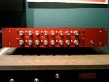
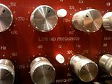
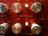
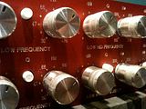
and some more inside pictures

http://i391.photobucket.com/albums/oo352/arnolievens/calrec/IMG_0518.jpg
http://i391.photobucket.com/albums/oo352/arnolievens/calrec/IMG_0519.jpg
http://i391.photobucket.com/albums/oo352/arnolievens/calrec/IMG_0522.jpg
http://i391.photobucket.com/albums/oo352/arnolievens/calrec/IMG_0514.jpg

Fpd file emailed.

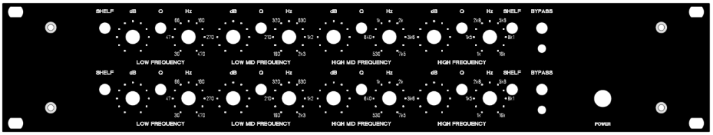
Panel was made by schaeffer-ag and has no infill. Might be more readable with white text.

You should pay attention with the pots. The dual 100KC pots are hard to find so it will depend on them which size you use (10mm, 8mm or 1/4" holes and spacing from the pcb)
I used omegs from AML for freq and vishay spectrol cp pots for boost/cut but their solder pins turned out to be too short...
You might wanna wait with soldering the spun switches in completely. I started out with one pin first, and repositioned after the pcb was inserted.
Actually, I did that after I replaced all toneluck switches for alps because they had longer pins and the pots didn't allow me to mount the switches flat on the pcb.
If I had to do it again, I would consider placing the Q switches higher on the front panel, which was designed for smaller pots than the omegs. But I'm really happy with the result I have now.
 
I'd love to get that FPE for myself as well. I have a set here waiting for metal too.

Email is by my name when your logged in.


Kevin
 
Hi Arno Great work!!! Congrats, it looks very nice and cool. I like the red color. I love your powersupply and the connector pcb also. Great work!! This encourrages me to keep this very high quality build.

Thanx a million times. I have my pots and switch caps (except 2 :'() from an old eela module. They are already soldered on the pcb's, I hope this is not a problem.

You could post it here in your own thread or in the group account. A lot of people would be happy.
 
nope, it's home-etched so I only made one.

I could look for the layout though.
It has to be somewhere  :-\
 
Back
Top