Got me a board to recap, got me some questions

GroupDIY Audio Forum

Help Support GroupDIY Audio Forum:

This site may earn a commission from merchant affiliate links, including eBay, Amazon, and others.

Rybow

Well-known member
Joined
Aug 18, 2009
Messages
782
Location
Edmonton, Alberta
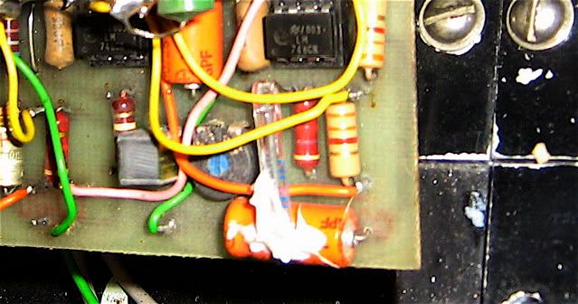
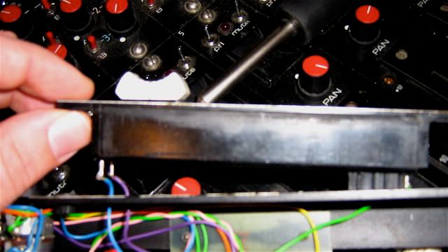
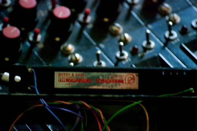
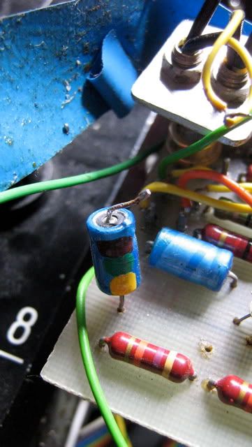
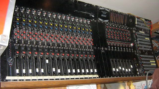
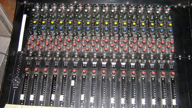
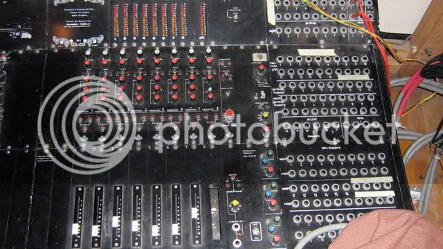
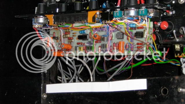
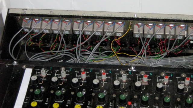
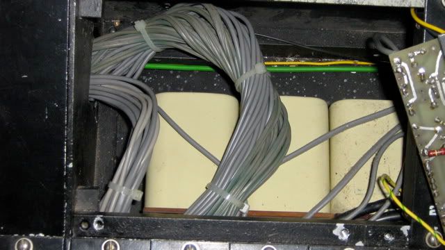
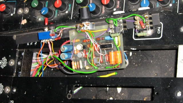
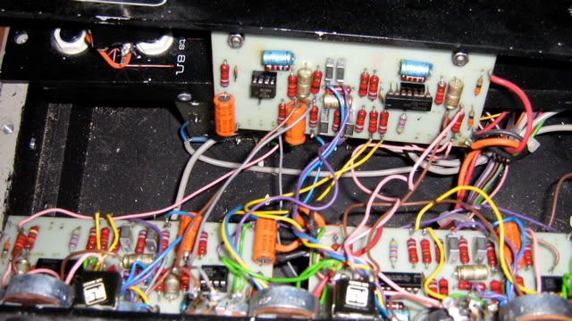
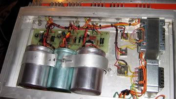
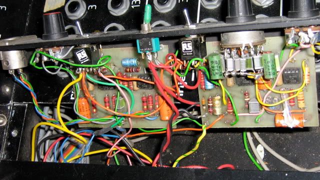
Hello! I have a huge project sitting in my basement, and I have finally decided to get to it. Its a 16 channel mixing desk built in 1977 by a company called Palace Acoustics. I have been informed that Palace Acoustics was formed by a couple of engineers from Midas. I did email Midas about it, and they did tell me it looked like a vintage Midas board, but then they stopped talking to me, and I can't find any info directly related to Palace Acoustics. Anyways, it needs a recap. It sat in storage for 10 years before I got it, and has been modified to hook directly in to a 16 channel reel to reel. The whole board is set up for bantam TT. The board was last used to mix sound for films. I am looking at recapping the power supply, 2 channels, 2 monitoring channels, and the master output section to start. Also clean all the pots and faders. Will this be enough to give me a good idea about the sound of the board? Are there any other things I need to be aware of? I am going to start pulling values off the caps today. Thanks in advance! Here are a couple of pics of the board. I'll add some of the inside as soon as I can.

Fullboard.jpg


channelsection.jpg


routing.jpg

 
Here is some of the inside modules.

Channel strip:
Channelstripinside.jpg


Input section
inputsection.jpg


Underneath a panel that says "Danger, 15000mV, do not remove cover"
powersupply.jpg


Headphone and monitor level control
monitoringstrip.jpg


The "Producers module" on the top, connected to 3 Aux sends each with a Gain, Treble, and Bass control
Auxsends.jpg


I ran some audio through it a long time ago going in via the channel inserts. The level fluctuated, and the sound was really dark. The EQ's worked sorta, the faders would cut out when pushed all the way up. All the controls worked including the oscillator. That was awhile ago though, and I tried it again recently and couldn't get anything at all. I will try again soon though.

I decided just to get in there today. I had to pull up some of the caps in order to get their values. I just need to confirm a couple of things. A few of the caps have a number on them that is written 22/25 and 4.7/40. I assume this means 22uF/25V and 4.7uF/40V. There is one cap on the fader circuit that is way different. It has a 3 colour code that looks painted on. From the positive to negative terminal, the colours are grey, blue, yellow. I looked this up, but could only find info on 6 colour codes for mica caps. Thoughts? I have all the other caps on channel one mapped except this one.
 
I'm not an expert, but here are some thoughts:

Start with one input channel.  Listen to its direct output & see what you think.  Then start messing with it if you so desire.

Check IC pins for tarnishing.  I had problems with that on some Auditronics channels.  Spraying Deoxit into the EQ pots might not be a bad idea.  Then maybe do some recapping, & compare the recapped module to one that's not recapped & see what you think.

Faders look like they might be EAB or something similar.  If so, you can probably fix the problem at the top of the fader throw by making some mechanical adjustments within the fader.  

Those are my thoughts anyway.  Good luck with the board!
 
Last but not least, the power supply. Mega caps!

powersupply-1.jpg


I have the whole board mapped out now. Luckily, there are very few different cap values which makes it easier. To do 2 channels all the way through, I am looking at around 90 capacitors. To do the rest of the channels all the way through is over 300 caps. Crazy! If anyone is in Vancouver and is looking for some soldering practice, let me know!

Just have to nail down these colour coded caps. I found another one, but this one is + red, green, yellow -. I believe the + gray, blue, yellow- cap is 3.3uF/40V. Let me know if I got this wrong.

Looks like a lot of work, but someone put in a ton of work hand wiring and soldering this board, and I want to know what it sounds like!  ;D
 
hodad said:
I'm not an expert, but here are some thoughts:

Start with one input channel.  Listen to its direct output & see what you think.  Then start messing with it if you so desire.

Check IC pins for tarnishing.  I had problems with that on some Auditronics channels.  Spraying Deoxit into the EQ pots might not be a bad idea.  Then maybe do some recapping, & compare the recapped module to one that's not recapped & see what you think.

Faders look like they might be EAB or something similar.  If so, you can probably fix the problem at the top of the fader throw by making some mechanical adjustments within the fader.  

Those are my thoughts anyway.  Good luck with the board!

Hey Hodad! Thanks for the reply! Good tip on checking the IC's. There are certainly a lot of those, and I did notice some crud on some of them. The faders in this board are all P & G. People have told me to put them in a bucket of water to soak and stuff like that. I'll look for an adjustment on them.

I was going to power it up today and see if I can get some audio through it again, but as I was mapping it out, I noticed that there are several caps on the oscillator card that are blown. So I don't think I'll be powering it up anytime soon. Speaking of the oscillator, here is a pic:
oscillator.jpg


There is an orange cap in the lower right hand corner with a bunch of white goop on it. Coming out of the goop is what looks like a glass tube that is soldered onto the circuit board. Is this normal? This is the first mixer I have ever taken apart/owned so this is all new to me.

 
For pot cleaning, probably better to use CaiLube than DeoxIt. CaiLube includes a lubricant that keeps the sliders moving smoothly.

If you're going to replace the big power supply caps, Vishay-Sprague 36D (or their new lead-free equivalents) have an excellent reputation for longevity.

Peace,
Paul
 
Insomniaclown said:
Speaking of the oscillator, here is a pic:
oscillator.jpg


There is an orange cap in the lower right hand corner with a bunch of white goop on it. Coming out of the goop is what looks like a glass tube that is soldered onto the circuit board. Is this normal? This is the first mixer I have ever taken apart/owned so this is all new to me.

Looking at the picture, it reminds me of a temperature compensation mod on the DBX 202 XTC VCA's that I have in my SSL console. I've never heard of a TC on a cap, but I'm pretty new into electronics as well....

Thinking of it, it could also be for thermal coupling of 2 caps.

The white stuff...is it fluid or is it some kind of glue ?

Can you post a close-up picture ?
 
it is a light bulb. this is used as a thermistor to limit the gain of the oscillator.

glued to the cap just to keep it in place.

Pretty old school version of a Wien-Bridge-Oscillator. Nice.

 
One more thing on the faders:  if they do happen to be EAB or similar (i.e., wiper travels down a strip of tapered carbon impregnated on a piece of phenolic, any sort of lube is likely unnecessary & possibly a bad idea.  I've been working on mixer channels with EAB faders, & even though the channels were obviously stored for years in less than ideal conditions, the faders are absolutely noise free--and any cleaning/lubing is accomplished via other means. 

So how about a pic of one of the faders? ;)
 
Thanks for all the responses!

pstalmer- I'll get some of that Cailube for all the faders and pots. I guess I'll need both the 5% and 100% solutions. I looked at the power caps, and the 2 big silver ones are the Sprague 36D's you mentioned. The blue one is a Daly cap and the can looks like it has been crushed a bit on the bottom.

Here is a close up of the oscillator. I am glad to here that it is normal! The white stuff definitely looks like glue. When I go to replace this cap, what type of glue should I use, and what type of light bulb do I need? I'll look up that Wein-bridge-oscillator. Thanks for the info!
oscillatorclose.jpg


Here are the faders from the side and bottom. They are Penny & Giles model 18201 1K. They still feel pretty good. I did some air dusting on them already. Pulled out some pretty serious dust clumps. Nasty. I did try some stuff from MG chemicals. A contact cleaner with a silicone lubricant. In order to fully pop them out I need to desolder the wires connecting them. I have heard that it is possible to take faders completely apart, but these don't look like they can be easily pulled apart. All suggestions on cleaning these are most welcome!
Faderside.jpg

faderbottom.jpg


One more question. Is there a resource for capacitor colour codes? I still have one electrolytic that I can't place. It goes +red, green, yellow-. I have found info on 6 colour codes, but not 3 colour codes.

Thanks a lot guys!
 
Insomniaclown said:
One more question. Is there a resource for capacitor colour codes? I still have one electrolytic that I can't place. It goes +red, green, yellow-. I have found info on 6 colour codes, but not 3 colour codes.

Going off my color coding skills.

Red = 2
Green = 5
Yellow = 4

So 25 * 10000 = 250000pf or .25uf.

Which seems pretty small for a electrolytic, perhaps my calculation is wrong and it's 2.5uf.

Mark
 
I am not too sure what it is. I had another one of these situations in the board. One module I have is made up of 2 matching cards. On one card is a cap that is +grey, blue, yellow-. On the other card in the same position is a 3.3uF 40V capacitor. Weird. Tried to do a measurement with the old DMM even though I know it wouldn't be entirely accurate. My supposed 3.3uF caps measured at 9.3uF, and the other one that I don't know measures at 4.7uF before falling to 3.3uF. This is with one end disconnected from the circuit. There is zero writing on these caps.

Here is a pic:
capacitor.jpg


I am having a couple of issues getting the power caps sorted. The big silver ones are 35000uF Vishay 36D's. 35000uF seems to be an obsolete value, so the next closest values are 34000uF and 36000uF. I have more options in the 34000uF category, but would that work?
 
So I emailed Vishay about the above capacitor. I thought the outside packaging looked a lot like current production Vishay capacitors. They just got back to me about them, and it would appear that they are not Vishay caps. I am not quite sure how I should proceed on this one. Any suggestions? I unfortunately don't have a schematic to work off of.
 
That cap looks like someone cleaned off the original manufacturers printing and then blobbed on a "house" colour code!
 
Crap. That's what I feared. Anyone know common house colour codes in Bath England in 1977?

How should I proceed here? Just throw something in that is a similar size? There is very little variation in the different values on this board. So if I find another cap on the board that is a similar size, could I just try that value?
 
The simplest (and probably smartest) thing to do is to leave it in there.  You have no idea of the value, no idea why they color-coded it, so as long as the old cap's not completely bad, it's probably better than just guessing at it.
 
Wow! Way mojo! Awesome eye candy, Love all the switches. my 2 cents on the cap is try to figure out what the capacitor does. IF its a coupling cap you could get away with guessing its value maybe 10uf - 47uf? If you can try to guess the impedance of the surrounding circuit, by looking at the resistor values. if they are all super high like above 100k or something then the smaller the cap value and probably the more important it will be to get the value right. but most likely its mid to low impedance - 20k or less, I'm not expert by any means, but if you can find out where it comes from and where its going then you can figure out what size to replace...
anyway Good luck! looks greeeaaat!
AC
 
Hey abechap024! I love all the switches too. I am thinking there is still some mojo in this board. The more I get into it, the more excited I get about hearing the sound! Little ways off though. Got a lot of sourcing to do.

I will investigate the caps purpose in the circuit. See if I can get a ball park figure. I'll also desolder the one next to the one I pulled up and measure it. The one I pulled up tests as bad, but the other one may be OK.  I'll get working on those resistors as well. The circuit is part of my main stereo monitor control, so I should do my best to put the right part in there.

I just found out that the guy who gave the board to me is still in contact with the guy who used to service it, so I may be able to get some more info that way as well. Unfortunately, the guy who gave me the board hasn't got a clue about it. He was the studio owner, but was more involved in the filming aspect, not the mixing.
 

Latest posts

Back
Top