troubleshooting ampeg SVT350

GroupDIY Audio Forum

Help Support GroupDIY Audio Forum:

This site may earn a commission from merchant affiliate links, including eBay, Amazon, and others.

ward

Well-known member
Joined
Jun 4, 2004
Messages
348
Location
Belgium
I'm troubleshooting an ampeg SVT350.  The owner ripped the eq faders off while putting it in the trunk.
He doesn't mind very much for the faders as he never uses them.
In the beginning it was making crackling noises which turned out to be a bad ground connection.
I managed to fix that.

Now I'm searching for another problem.
The fan never works, the relay that switches the speakers in and out works most of the time.
The schematic of that part is here:
Ampeg_B2_SVT350H.jpg

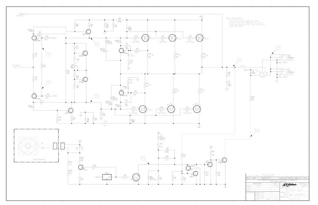
The full schematic can be found here.
http://www.filestube.com/92534ccf524b9af303e9,g/Ampeg-B2.html

I made some measurements,
the fan works when connected to a 9V battery.  Out of circuit it measures 250k. It's a 24Vdc model.
When the fan is out of the circuit there's about 55V on it's terminal,  when connected this drops to about 2V.
ampeg.jpg


The official schematic is not completely consistent with my handdrawn one.
That's because the amp is an earlier version.
It doesn't have ic1 to control the fan.

Anyone has an idea on how to troubleshoot this amp ?
Do the voltages around the transistor seem ok ?

What could be the cause of the voltage drop when the fan is connected ?
 
What you hand drawn schematic looks to be doing

The 1.5K on the left is always in circuit and I guess selected for min fan speed.  If the transistor is turned on the voltage drop across both the 1.5K leg  and the transistor leg will drop and the fan will turn faster(less resistance).  May guess would be a bad 1.5K maybe it measures higher than 1.5K OR bad connections broken solder at the connector to PCB.

Think about it, with the fan disconnected there is no current in the 1.5K(well maybe some leakage of the 220uf cap and the small meter load)
You connect the fan and get only 2 volts across the fan connector?  

EDIT  I would measure the fans current draw when powered by a 9V battery.  Maybe the fan draws to much current causing a higher voltage drop across the 1.5K.  A dot matrix printer I repaired used a higher voltage fan as a two speed.  After time the fan would only run at the higher speed(voltage the fan was designed for) and the power supply in the printer would cook because the fan only went to high speed when printing.  Something changed in the fan, bearing going bad, part value(s) drifting who knows.  Changing the fan before the power supply burned often fixed the printer
 
Thanks for that explanation Gus,
I can check those clues tonight.

what puzzles me is that if the resistance reading of the fan is correct,
almost the full 60Vdc is on the fan ?  While it's only a 24Vdc model ?
 
The Fan is most likely a DC brushless, So there is a circuit inside.  The resistance reading is when the circuit is off.  Often there is a round magnet mounted in the fan blade section and a fixed four pole wound core.

A page I found with google

http://www.comairrotron.com/brushless_dc_fans.shtml
 
Thanks Gus,

This is the fan:
http://www.comairrotron.com/cgi-bin/dcfandatasht.pl?Pnum=032127&airflow_unit=CFM&pressure_unit=inh2o&diameter_unit=in

I did some measurements,
the fan on a 9V battery pulls about 30mA.  It's maximum rating is 0,14A.
That seems ok to me.

I measured the 1K5 resistor and it measures ok.  I reflowed the solder joints.

Now I did some more measurements at the transistor:
  with the fan connected :  0,3V
                                      62V
                                      0,001V
  fan unconnected : 0,3V
                            8,5V
                            0,001V


I might have misunderstood your first post.

To be clear do you meant the voltage at the two fan terminals drops to 2V from terminal to terminal?

The lm35 is temp IC.  It looks to be driving both the base of the transistor for the fan speed control and protection circuity that controls the speaker relay
http://www.national.com/ds/LM/LM35.pdf

What drive the base of the amp version you are working on I ask because it might be driving the protection circuit that controls the relay.
 
Gus said:
To be clear do you meant the voltage at the two fan terminals drops to 2V from terminal to terminal?
Yes.

Gus said:
The lm35 is temp IC.  It looks to be driving both the base of the transistor for the fan speed control and protection circuity that controls the speaker relay
http://www.national.com/ds/LM/LM35.pdf
I believe I have an earlier version of this amp without the LM35 temp control.

Gus said:
What drive the base of the amp version you are working on I ask because it might be driving the protection circuit that controls the relay.
Do you mean : What drives the base of the Tip31C transistor ?
I will have to trace the board a little more to know that.
 

Latest posts

Back
Top