Standardized Card Edge for All Future 500 & 51x Projects?

GroupDIY Audio Forum

Help Support GroupDIY Audio Forum:

This site may earn a commission from merchant affiliate links, including eBay, Amazon, and others.
Solving the Eagle height problem.

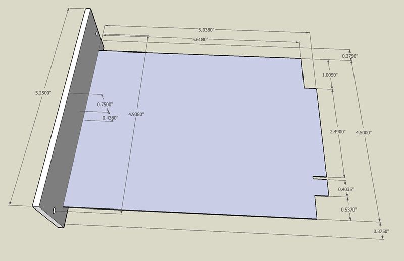
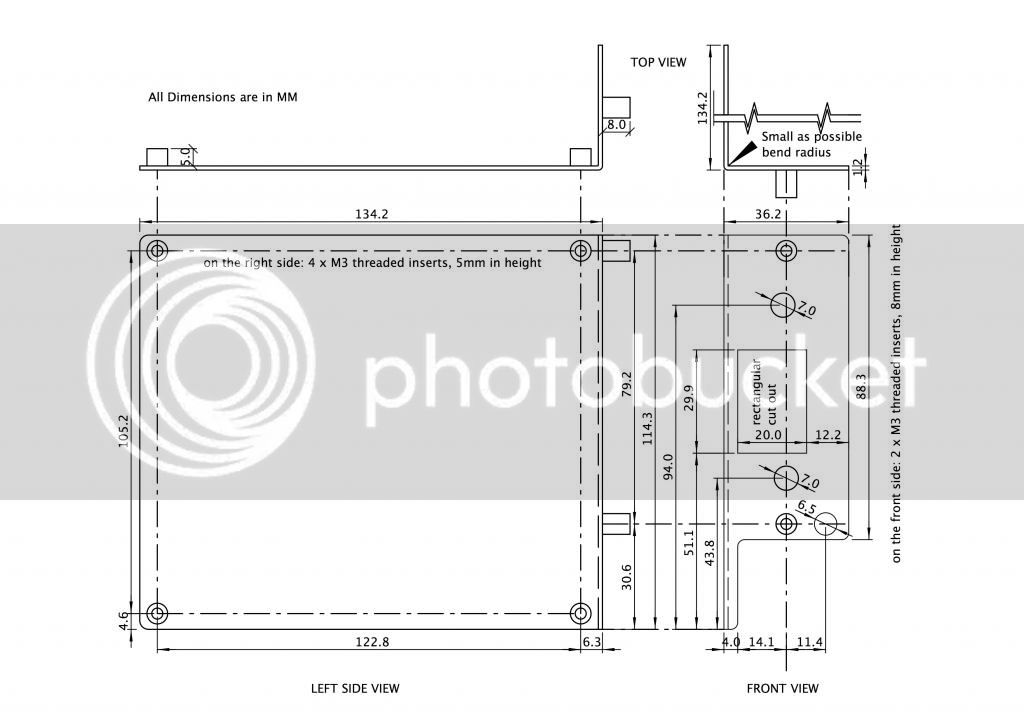
Some eagle versions have size limitations that prevent putting grounded mounting holes on a 4.5" tall card.

It is no problem for eurocard sizes, but plays hell with 51x sizes.

But this can be solved in the following conditions:
1) The part contains the holes
2) The part is placed by the package command rather than add.

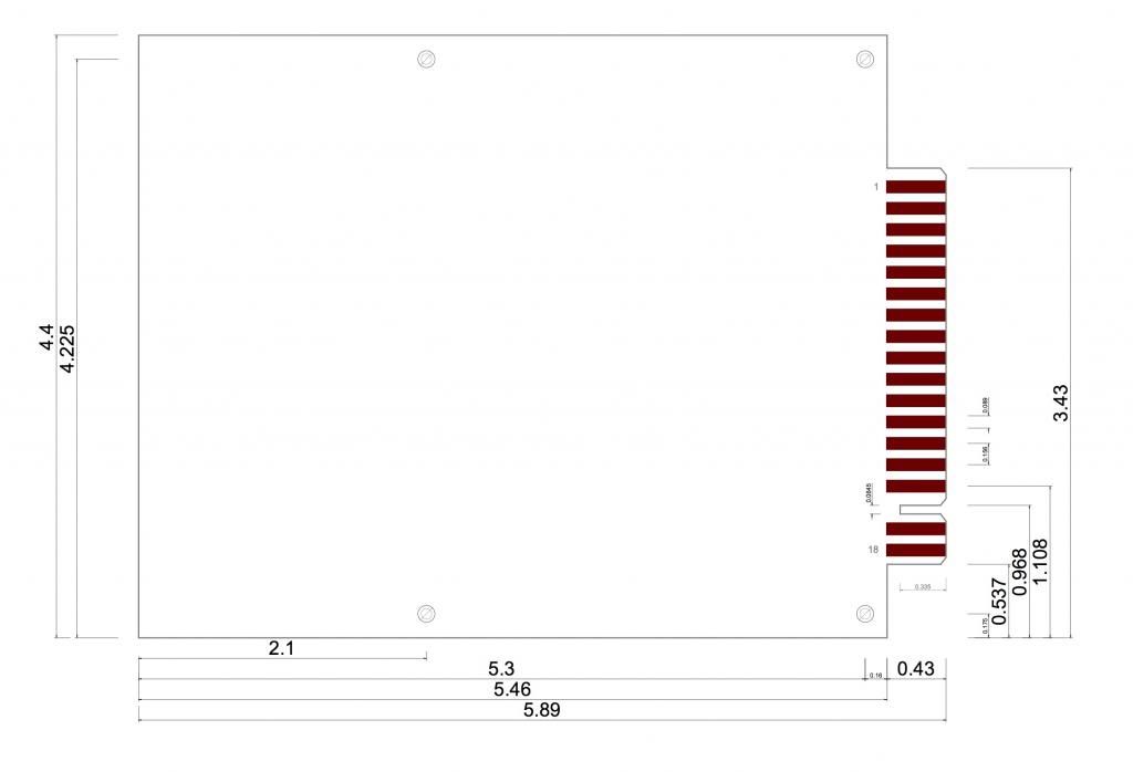
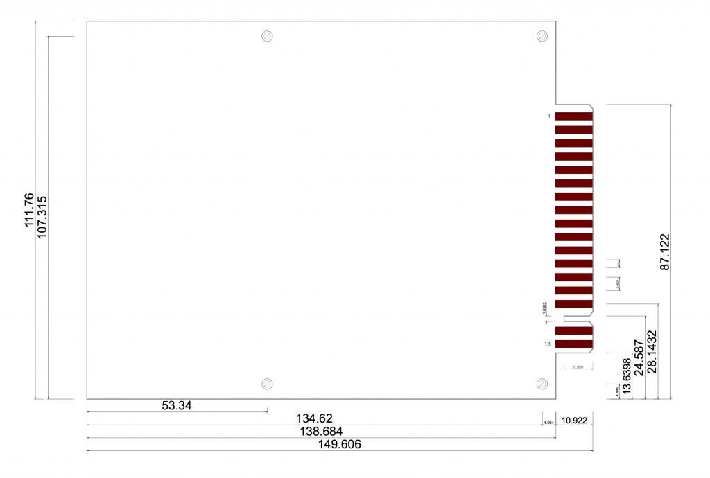
So what you do is make a part that has drills for the holes (no pads).  Then make an identical part that has the pads.  Then you just substitute the package.  (this works fine if you don't have anything connected to the pads, and the part places exactly where the previous part was).  Then you can connect nets and route to the pads with no problem.

However, if you want to change the part, you need to delete the net connections in schematic to the pads or the part will shift when you change it.  But it is really not much of a hassle.

The attached library has both versions (pads and no pads) to allow this.

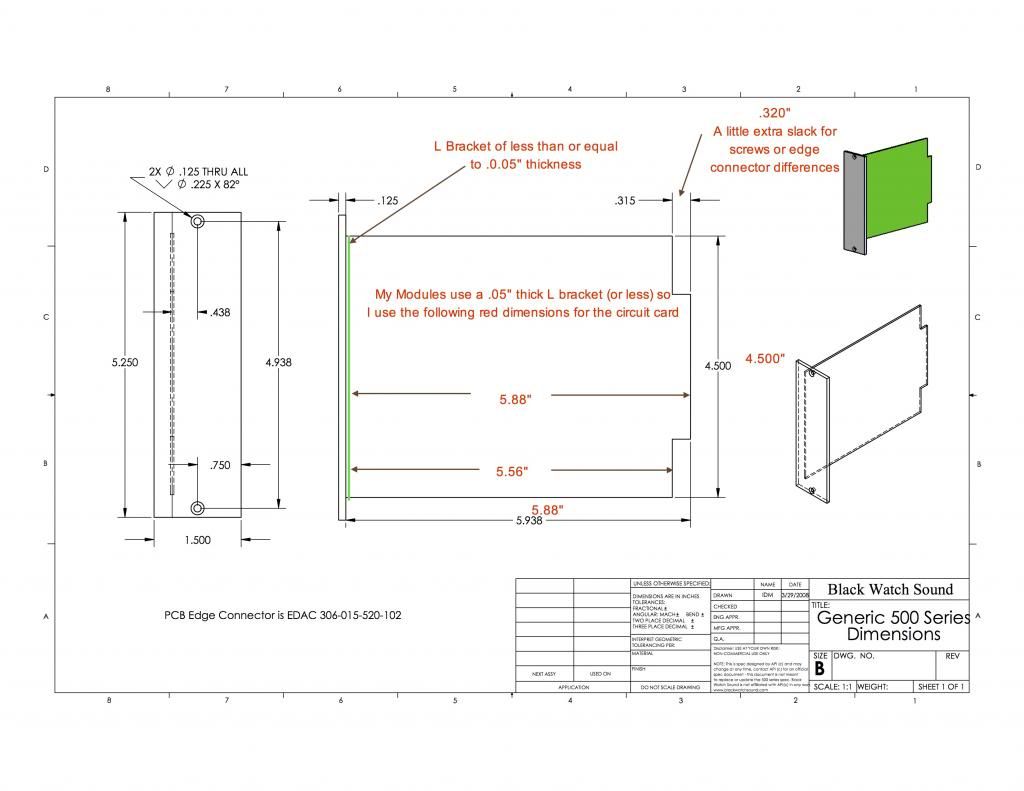
This doesn't let you place parts outside the area that you are allowed with your version of eagle, but it does let you make a 500 or 51x card that you can ground to the chassis, which is nice.

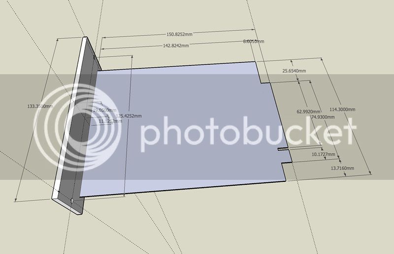
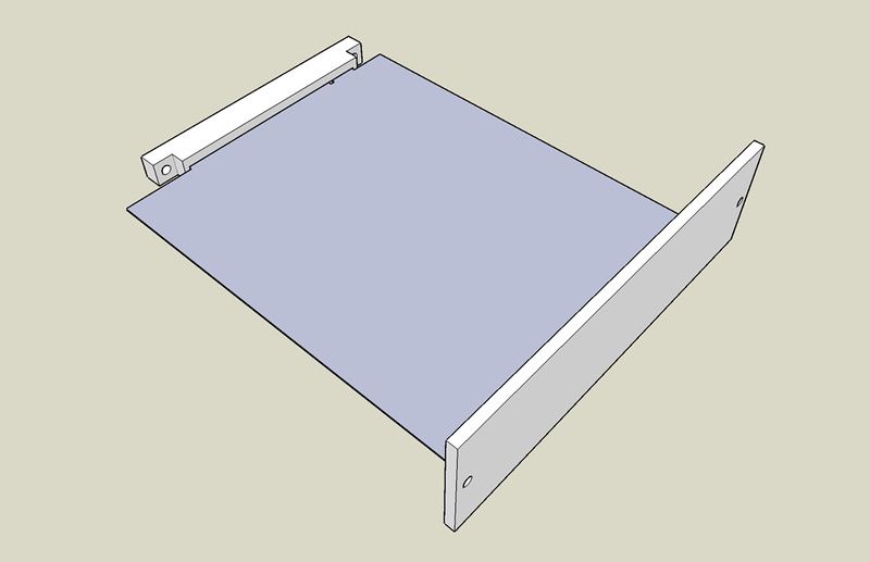
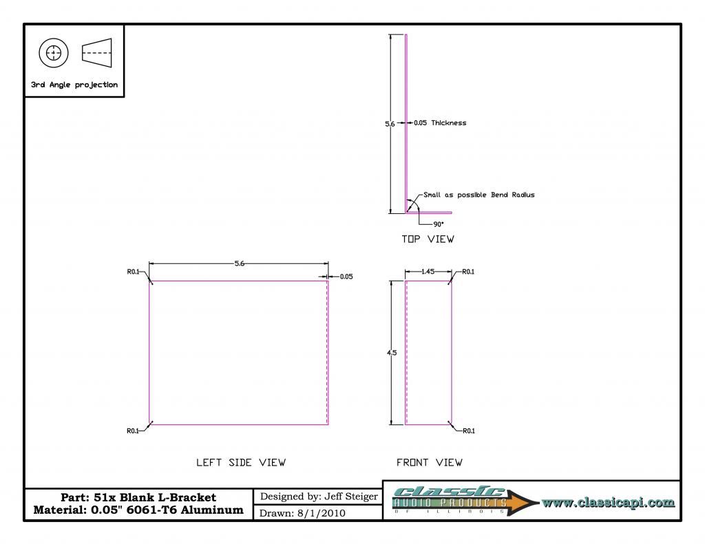
I have modified the attached library to have various 51x card sizes that leave space for a .05" carrier.  Not sure if or where I got the original version of this from but I am happy to credit that person if he or she exists.

Working on a card now that I will have manufactured, but I have not used this part to manufacture yet, so use at your own risk.  I have tried to place the holes and pads per the discussion in this thread.

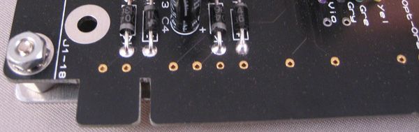
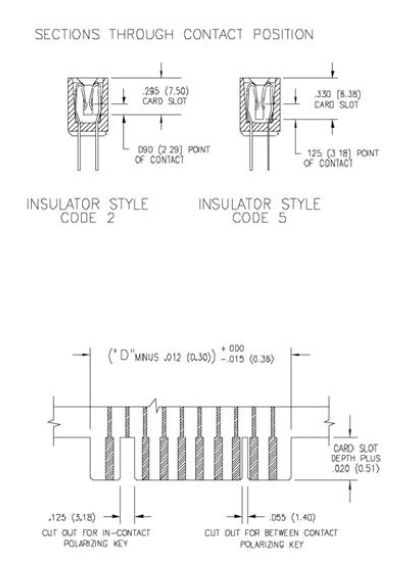
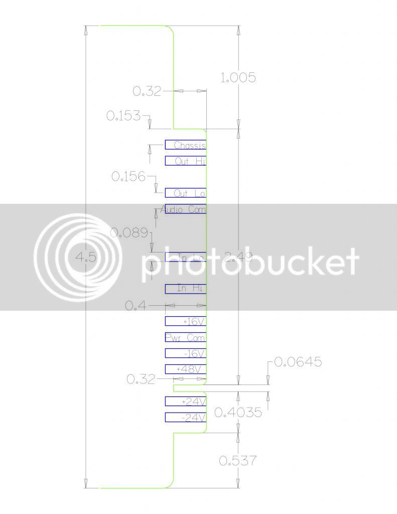
Also I like to have solder patch holes on each pin, I make them by routing a wide top trace on each pin to a location just next to the gold finger, and then switching to bottom routing (and eagle will make a via), and then routing back to bottom (otherwise the top and bottom goldfingers are not connected because they are just SMD pads).  I use a via with a nice size drill hole, this connects top and bottom pads and provides a hole for later patches.


Attachments

  • 51X-Carrier-Version.lbr
    52.4 KB · Views: 175
I saw too many variations on this forum for GroupDIY51X standard and decided to look for myself from internet. Idea is good and based on the existing API 500 with the addition of 2 more connections for +/-  24v power supply, other things remaining the same, for some people it is difficult to copy EXISTING dimensions. DataSheet from Radial Engineering Ltd. is most accurate information and hardly anyone wants to check. I tried with 18PINEDGE - Eagle Library but was opposed with document from Radial and decided to create maximally accurate Library with a combination of what I found so far. If I'm wrong somewhere, please correct me.
 

Attachments

  • 18PINEDGE - EAGLE test PCB (mm).pdf
    5.1 KB · Views: 264
Thanks MiTkO, I have been looking around the various threads for a long while and was quite puzzled by the variations in design measures and by the lack of an actual "final" thread or post with definite correct dimensions. I was about to mail Radial to get a copy of their spec sheets.

Spino

P.S.: by the way, many older threads say the docs have been uploaded to the groupdiy gmail account, which, for what I understand, doesn't exist anymore. Most of the docs that were there have been moved to the technical documents sections but the 51x dimentions don't seem to be there.

MiTkO said:
I saw too many variations on this forum for GroupDIY51X standard and decided to look for myself from internet. Idea is good and based on the existing API 500 with the addition of 2 more connections for +/-  24v power supply, other things remaining the same, for some people it is difficult to copy EXISTING dimensions. DataSheet from Radial Engineering Ltd. is most accurate information and hardly anyone wants to check. I tried with 18PINEDGE - Eagle Library but was opposed with document from Radial and decided to create maximally accurate Library with a combination of what I found so far. If I'm wrong somewhere, please correct me.

Thanks MiTkO! 

From the "Everything is more complicated than it seems" category....
Two additional measurements would be desirable on your document.

1) State whether the length includes the carrier (L Bracket) or whether it goes right to the front panel.
2) State where the holes are (how far apart vertically, and distance from front panel. 

This would help make the carrier (L Bracket) holes compatible with other cards (there is no standard, but I think we would like to adopt what [silent:arts] and Classic API are doing for the back holes.

FYI Chunger had provided measurements (without holes) the depth differs from yours (probably due to allowance for carrier (L Bracket)), you can find them through the 500 51X META but a direct link to one copy is http://groupdiy.com/index.php?topic=41919.msg521950#msg521950.

Note, not that it matters to me, but on principal I have never inquired with Radial because they seem to require an agreement to use and credit their proprietary trade names on certain pins and give them certain marketing rights, specifically:

The Recipient grants Radial Engineering Ltd. the right to:
a) Publish my name, company logo (if applicable) and any name associated with a product I am developing for use in any and
all of Radial Engineering’s marketing initiatives.
b) Take photographs or video that may contain my likeness as well as the likeness or image of my property (product).
c) Take, record and publish testimonials or other statements from me and to use these for commercial and business purposes
in any marketing initiatives.

 
hi emrr, are you referring to a doc on the group's technical pages or you're simply saying it's possible to contact radial and have it through them?

emrr said:
You can certainly download the Radial standard and read it.
 
Spino said:
P.S.: by the way, many older threads say the docs have been uploaded to the groupdiy gmail account, which, for what I understand, doesn't exist anymore. Most of the docs that were there have been moved to the technical documents sections but the 51x dimentions don't seem to be there.

Just expand an existing VPR with 3 x EDAC Pitch and you are done?
Pin1 stays on top. Nothing more.
While I would like I do not understand the problems.

(Radial Docs won't help here, they are VPR only)
 
I repeat, my puzzling came from the fact that in this very forum i found at least 4 or 5 different board sizes. And I'm not referring to the general size, which could be a manufacturer's choice, but to the part where standard specs would be of help. I found it funny that allowances were down to a fraction of a millimeter and then different designers varied their sizes to orders of magnitude greater. Also, many of the docs that are referred to were on the now defunct gmail group account. I guess I'll go that way then: ask radial for (not theirs) vpr specs doc and then adapt for 51x pinout.

[silent:arts] said:
Just expand an existing VPR with 3 x EDAC Pitch and you are done?
Pin1 stays on top. Nothing more.
While I would like I do not understand the problems.

(Radial Docs won't help here, they are VPR only)
 
Here is sort of a "Mechanicals Meta".

Please let me know by PM if you have a link to one I have missed:

Chunger's

English
p390893387-4_zps32b094bd.jpg


Metric
p839474861-4_zps27eadbea.jpg


English and Metric
p866426053_zpsc9f4176b.jpg


Full PDF's of connector specs

Mouser EDAC
http://www.mouser.com/ds/2/123/44_305-315-35520series20new-194266.pdf

Classic API OUPIIN
http://www.classicapi.com/catalog/images/gallery/connectors/8706.pdf


p493630706-4_zpsf3af5abe.jpg


[silent:arts]
The Best description of a carrier hands down!
From the jensamp carrier you can figure out where the back holes on the PCB are supposed to go (by subtracting lengths).

Metric

Jensamp

silentartsJensamp51X_Lrev02_zps0c1beb06.jpg


http://groupdiy.com/index.php?action=dlattach;topic=39897.0;attach=26280

OV560

silentartsOV560_Lrev02xB_zpsa9b112ce.jpg


http://groupdiy.com/index.php?action=dlattach;topic=39897.0;attach=26281


51x-18-pin-notch-layoutdimensions_zpsa81ed9f7.jpg

http://www.classicapi.com/catalog/images/gallery/GroupDIY/51x-18-pin-notch-layout.pdf

MiTkO's

English
18PINEDGE-EAGLEtestPCBInch_zpsac4401c8.jpg


http://groupdiy.com/index.php?action=dlattach;topic=39897.0;attach=25104

Metric
18PINEDGE-EAGLEtestPCBmm1_zpsc11dc465.jpg


+http://groupdiy.com/index.php?action=dlattach;topic=39897.0;attach=25103

Classic API's

Blank-Bracket-for-pdf_zpsde46989c.jpg


http://www.classicapi.com/catalog/images/gallery/GroupDIY/L-bracket/Blank-Bracket-for-pdf.pdf

Vince@Speck

SpeckASC-VMechanical-500SeriesDimensions_zpsf8d0ae00.jpg


http://groupdiy.com/index.php?action=dlattach;topic=39175.0;attach=3729

Black Watch Sound

500SeriesSpecDWG-Sheet1_zpse619c1e3.jpg


With notes
500SeriesSpecDWG-Sheet1annotated_zpsceaf8878.jpg


Other/Unknown

APInormal_cutout_zps2ac0a463.jpg


Mechanicals Meta

The purpose here is to bring together references to what mechanical data is available for the 500/51X series in a visual way.  That way when looking for a particular dimension it is easier to figure out whether someone has described it.  Where the images are in PDF form, I will link the existing PDF and provide a readable JPEG version.

Please send any updates to me via PM, and I will post them.

The images are not my work, if you want your image taken down just say so.

And some "Roots" images  :) from the "What are we doing and how big is it?" department

slender chap
prodigy_module_zpsa68bfed8.jpg


peter purpose
rack_zps4b6ca285.jpg


kato
milemarkers_zpscb843e97.png


Jeff Steiger
Card-edge-close-up_zpsd96a69cb.jpg
 
It would be great if one could get a pre-drilled carrier or box for a module (full metal jacket)... But where would the holes go?
You will note that none of these documents specifies where the mount holes go.  That was my original intent in trying to make eagle parts with mount holes specified.

OV560 Template is a good example of spec'ing where the holes go.  We like!
 

Attachments

  • silent arts OV560_Lrev02xB.pdf
    23 KB · Views: 118
bruce0 said:
It would be great if one could get a pre-drilled carrier or box for a module (full metal jacket)... But where would the holes go?

You could use the JENSAMP-51X L-Bracket as a template.
The wholes are done so the prototype card edge connector will fit.
If I recall correctly I overtook the whole placement from Jeffs VP2X.
 
Thanks Volker:

I got your OV560 template and your Jensamp Template, which are both IDEAL examples of how a template should be drawn, but I didn't know it was ok to post and I hadn't gotten around to asking.

bb

Jensamp - which says where the holes go.  We like!
 

Attachments

  • silent arts Jensamp51X_Lrev02.pdf
    22 KB · Views: 131
Has anyone created a basic pcb layout template as a standard for 500 series boards yet?  By that I mean a board outline with connector pads, the 4 standardized( classic API layout?) mounting holes , cutout at pin 16 and maybe a single hole pad at each pin plus silk screen for pin functions.  Otherwise a blank board. A gerber file of this for everyone to start with as a template would be a way to further the standard discussed here. It will also keep novice pcb designers from having to  "recreate the wheel" so to speak. Lotsa work for a novice to get the connector pinout and cutout right.
 

Latest posts

Back
Top