


Sammas
Well-known member
I've been noodling around with my Amek BCII. The mic input's were bypassed
to act as a second line input stage. Reversing it was pretty straight forward,
but a few channels are suffering from loud "pops" when the 48v is engaged. I'm a
little worried this will damage a mic or such.
What is causing this? Perhaps small variances in the 6K8 resistors? I used 1% tolerance
and matched them with a DMM as close as I could. Is this generally adequate? Perhaps
the pushbutton switches are on their way out?
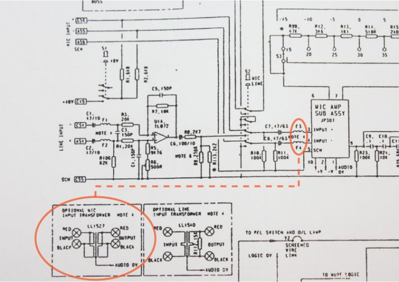
Also, I've added some transformers prior to the mic input stage as outlined here in the schematic
below. The transformer effectively replaces a pair of ferret beads, but there is no additional information
regarding installing the transformers in the manual. They are installed, sound great but is it possible to now
remove the two coupling caps prior to the transformer? I don't see why not? Would the popping (possibly mismatched)
48v cause a problem with the transformer primaries?
to act as a second line input stage. Reversing it was pretty straight forward,
but a few channels are suffering from loud "pops" when the 48v is engaged. I'm a
little worried this will damage a mic or such.
What is causing this? Perhaps small variances in the 6K8 resistors? I used 1% tolerance
and matched them with a DMM as close as I could. Is this generally adequate? Perhaps
the pushbutton switches are on their way out?
Also, I've added some transformers prior to the mic input stage as outlined here in the schematic
below. The transformer effectively replaces a pair of ferret beads, but there is no additional information
regarding installing the transformers in the manual. They are installed, sound great but is it possible to now
remove the two coupling caps prior to the transformer? I don't see why not? Would the popping (possibly mismatched)
48v cause a problem with the transformer primaries?