Pultec question (extended into pultec alternatives)

GroupDIY Audio Forum

Help Support GroupDIY Audio Forum:

This site may earn a commission from merchant affiliate links, including eBay, Amazon, and others.
bass almost drops to -10db @ 50kOhm terminated, but treble only down to -5db.
the 500k termination is part of the filter network, go directly to grid or fet for best linearity.

-max
 
This seems like a nice and reasonably flexible circuit to integrate into a preamp in an appropriate spot.

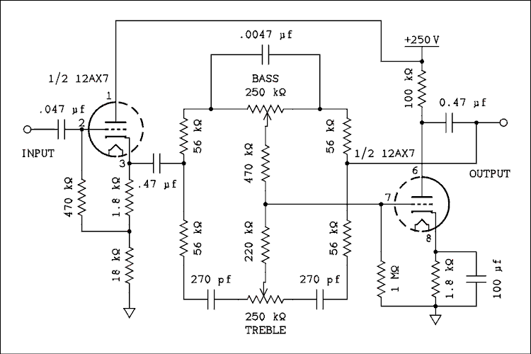
Amp-Tone-5-A-B.gif


How do I calculate the exact values for the capacitors in the filter circuit (47nF and those two 270pF)? Bigger cap is lower frequency quite obviously, but what's the exact formula?

I can always experiment, but would like to set exact starting values.
 
The formula you are looking for is well known F= 1/2pi R C. Re-arrange for C is simply C= 1/2pi R F. This is for the cut-off frequency.

Normally you would have two cut off frequencies on either side of the potentiometer but because the resistor values are the same you have one for each side. For the bass frequencies you have 0.0047uF interacting with 56K and for the treble 270pF with 56K. There is actually more to that in terms of the complete transfer function but for the purpose of simple explanation this would be sufficient (I hope).

I of course have to still work out the impedance at the output node on the previous question but some other night.
 
I'm implementing this circuit to spice up a simple preamp of mine. effectiveness/parts-count ratio seems nice.

Amp-Tone-5-A-B.gif


I'm not too fond of 12AX7 and could do several alternatives because I don't need the very high mu. The preamp alone has plenty of gain.

But a bypass switch for the filter network alone would be nice. How do I calculate the insertion loss for the network? And what about the effect of feedback from the plate? Just how much feedback does this kind of connection produce?
 
I've just made a Pultec and it wasn't the hardest project to make.

Why not try playing with just the parts of the circuit you really need?

It breaks down into 3 voltage dividers with one leg of each by-passed by caps or coil/caps to get the tone shaping.  If you want some air for your mic then just use one 10kpot plus a 10k resistor with the pot by-passed by the coil/cap combination used in the 16kHz setting of the pultec and the output taken from the junction of the 2 x10ks.

 
Hi,

I have some questions about building the PEQ1a (http://gyraf.dk/gy_pd/pultec/gy_pd_sch.gif). For a mastering style version I only need 1/3 of the boost/cut range. This can be done by calculating the steps of the pots and replace them with rotary switched. A gain multiplier switch would be ideal, to switch between stock boost/cut and lower settings.

If I read the schematic correctly, there is a voltage divider of 10:1 by the 10k high boost pot and the 1k high cut pot. If I place a resistor between them of aprox 2k, then the totale range would be 10:3. But then the fixed gain make up would be too much. Is there an easy way to incorporate a cut/boost multiplier in this schematic that works with the fixed gain?

2nd question. There is a 200nF coupling cap between the filter stage and the SRPP. What type of interstage transformer would be ideal as a replacement?

THANX for the input!
Maarten
 
2nd question. There is a 200nF coupling cap between the filter stage and the SRPP. What type of interstage transformer would be ideal as a replacement?

Maarten,

If you look on Sowter's website there is one there under Pultec in the vintage section,  its 1:2CT type 9330.
This works very well.
DaveP
 
The concepts are entirely the same.  Particularly the bandwidth and shunt R experiments, and their relationship with required make-up gain. 

Here's a condensed revision of the bits in the MEQ500 thread:

http://www.proaudiodesignforum.com/forum/php/viewtopic.php?f=6&t=377
 

Latest posts

Back
Top