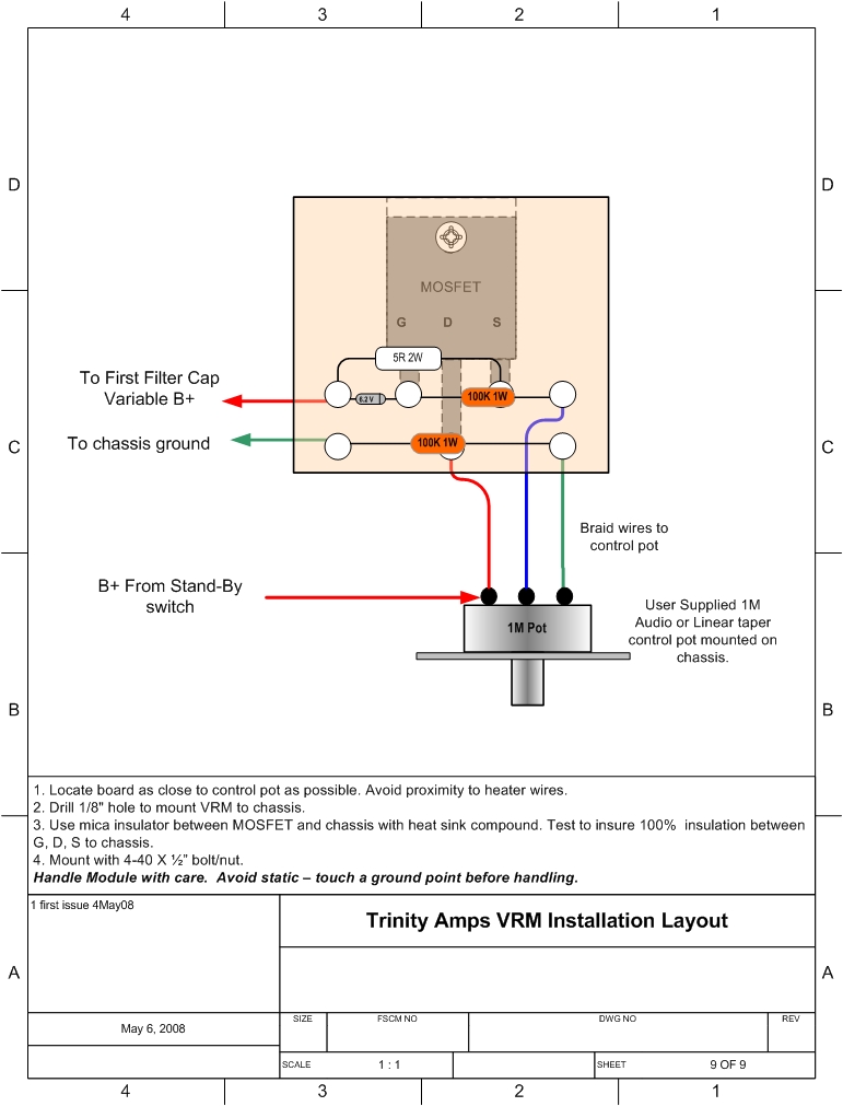
Mosfet regulated B+

GroupDIY Audio Forum

Help Support GroupDIY Audio Forum:

This site may earn a commission from merchant affiliate links, including eBay, Amazon, and others.

j.frad

Well-known member
Joined
Nov 12, 2008
Messages
236
Location
Brussels
Hi guys, I'm contemplating building a couple of tube micpres like the NYD one bottle and the PSU transformer I'll use will probably have a secondary that is too high.
I know I could just calculate and use series resistors to get the right B+ but I just stumbled upon this simple mosfet circuit, and I was wondering if it's worth using, I'd like to get the B+ pretty accurate.

VRM_installation.jpg

I might look overkill to oldschool tube circuit fans, that's why I bother asking you guys.
Cheers!
jules
 
> I'd like to get the B+ pretty accurate.

Why?

And what do you think is best?

Best performance comes with higher voltage. 600V or more. Even with "300V" tubes: resistor-loaded stages (like NYD used) only put roughly half the total supply voltage across the tube.

The flip-side is that performance improves slower than HEAT. And in commercial work, heat means more cost and less profit. That's so very true that we don't have a large choice of larger tubes with high gain.

IIRC, the NYD can go over 400V supply before the tube is stressed. The 2nd plate resistor will need to be 5 Watt (or three 2-watt parts).

> I could just calculate

It aint rocket science. Cut and try. While the NYD has two stages, the 2nd stage takes most of the current, so ignore the first stage. You know the 2nd plate resistor has a "large" drop. Pick a somewhat smaller resistor for dropping. Was it 15K?? Then grab a 5K, or 10K if your B+ is way-way high. Try it, then adjust. A 10-pack of 1K and 2K parts may be handy.

The MOSFET can work, of course. My "objection" is that small screw-ups can kill the MOSFET, and unless you are skilled in both theory and high-voltage diagnostics, you may not know what's wrong.

Also that plan puts HIGH voltage on the pot. Pots can be insulated for high voltage. But such use is rare, most pots are made small and CHEAP, I'm not keen to trust the internal insulation.
 
+1.    You are making it harder, with no obvious justification, and a circuit that has more ways to fail spectacularly. 
 
emrr said:
+1.    You are making it harder, with no obvious justification, and a circuit that has more ways to fail spectacularly. 

PRR said:
Why?
IIRC, the NYD can go over 400V supply before the tube is stressed. The 2nd plate resistor will need to be 5 Watt (or three 2-watt parts).

Thank you both, this is exactly what I was looking for. I am gathering knowledge about tube circuits and there's always a small thing or another that I am unsure of.
For example, An old western electric circuit say it can have B+ supply from 250 to 300V but I see people try to have B+ exactly at 300V on a NYD one bottle, these are almost the same circuits so do I really have to care? My power transformer is 280V sec. so unregulated B+ will be quite high but it may not matter. I don' know that, that's why I ask.
These are the simple details I sometimes have a hard time finding in the huge amount of info spread on the forum.

So I guess I'll skip the regulation and be tolerant with the tolerances;)

Thanks again to both of you, I have learnt much by reading your posts here and almost never had to post a question as everything is alredy covered on the forum.

One small question if I may, not really related to the subjects but related to the project: I saw it on the western electric app sheet and sometimes on the forum, that people reference the heater supply to something else than grouns, say 50V above ground. Why is that, and how do I implement it?
If my heater secondary has no center tap and do a fullwave rectification do I just connect the low side of the rectifier to a 50V tension?
Does it only work if I have a center tap on the heater?

Thanks again for your time, I hope my questions will be helpful to others! Cheers.
Jules
 
One small question if I may, not really related to the subjects but related to the project: I saw it on the western electric app sheet and sometimes on the forum, that people reference the heater supply to something else than grouns, say 50V above ground. Why is that, and how do I implement it?
If my heater secondary has no center tap and do a fullwave rectification do I just connect the low side of the rectifier to a 50V tension?
Does it only work if I have a center tap on the heater?


That is used to improve problems of AC heater hum that may be present. And as with the SS regulator on the PS circuit - Don't use it unless it's necessary.  Most of the time it is not.

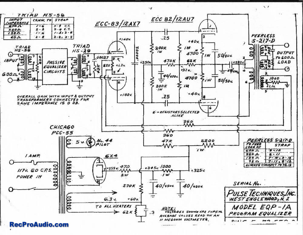
The original Pultec EQP1-A circuit is as good example as any of this type of arrangement. It's schematic is out on the web at several places.  A 250 -270K resistor + parallel 47-68K with .25 cap will get you in the ballpark in most cases.

If you are rectifying the filaments then you're going DC which is a different arrangement.  I wouldn't use DC for filaments unless it's absolutely necessary.

If your filament winding does not have a center tap, two 3W 100ohm resistors from each leg to ground should do the trick. If not, then substitute the resistors with a 100-200ohm pot - wiper to ground. If there's still small residual hum, try the elevation circuit in conjunction with the balance pot.

With this circuit, my guess is that using 6.3VAC, 2 100r resistors or a CT to ground and good wiring you won't hear a peep from the heaters.
 
> My power transformer is 280V sec.

400V raw DC sounds fine to me.

You will have to use a LOT of filtering to get the ripple down. You have L, C, and R. Using lots of R is "wasteful", but in today's world, L is costly. And you want to waste some voltage. So stone two birds at once: drop and clean.

That Pultec sucks about 16mA. From 400V to 300V is 100V drop. 100V/16mA is 6K resistance which must be added just to drop voltage.

The Pultec filter has a first cap and two R-C filter stages. The amp is push-pull; a single-ended ampl like the NYD has much less supply rejection and will need 1 or 2 more stages. Since we are not pinching pennies, pencil 4 R-C droppers.

Each resistor drops 1/4 of the 100V, 25V each, at 16mA. 0.4W dissipated. You always want to double-up, 1W part. There's a start-up surge so at least the first few ought to be very generous. 5W parts are not expensive.

So we need 6K in 4 hunks. They could be all 1.5K, or a mix of 1K and 2K if you can't find 1.5K in 5W. And if you buy a few extra in each size you can go four 1K for higher B+ (and ripple) or four 2K for lower cleaner B+. (Don't over-calculate. Use a hot iron and keen ears.)

The 40uFd (47uFd) is a fine value. I could compute the ripple but I know from hundreds of other plans that a 4-stage ~1K 40uFd filter can be sold without complaint.
 
Ah once again PRR strikes ;) This is great info, a perfect starting guide, I'm starting to get things a bit now.
Thank you so much!
 

Latest posts

Back
Top