You are using an out of date browser. It may not display this or other websites correctly.
You should upgrade or use an alternative browser.
You should upgrade or use an alternative browser.
Mitsos API 312 / 990 Build Thread
- Thread starter idylldon
- Start date


Help Support GroupDIY Audio Forum:
This site may earn a commission from merchant affiliate
links, including eBay, Amazon, and others.
mitsos
Well-known member
- Joined
- May 4, 2007
- Messages
- 2,886
Hi all,
All the parts I've been using are on the online BOMs.I will re-post the links to my first post on the first page. Once again Idyldon beat me to it!
Pins/sockets doubled in price this year. I think the last batch of sockets I bought were $20-25 per 100. There is another model that Niels said worked for him that are quite a bit cheaper:
0327-0-15-01-34-27-10-0
They are half the price of the others. I have not used them, but Niels said they fit. The only thing I am not sure about is if they have to sit flush with the PCB or if there's a trick to get them up more. I also think I remember someone posting that they drilled out the holes a bit and installed the ones at classicapi. If you do that, you will lose connectivity from between top/bottom pads so don't forget to solder the ground socket from the top.
Still writing up a brief doc with some ideas and such for all this stuff. Should have it done in a couple days.
cheers!
All the parts I've been using are on the online BOMs.
Pins/sockets doubled in price this year. I think the last batch of sockets I bought were $20-25 per 100. There is another model that Niels said worked for him that are quite a bit cheaper:
0327-0-15-01-34-27-10-0
They are half the price of the others. I have not used them, but Niels said they fit. The only thing I am not sure about is if they have to sit flush with the PCB or if there's a trick to get them up more. I also think I remember someone posting that they drilled out the holes a bit and installed the ones at classicapi. If you do that, you will lose connectivity from between top/bottom pads so don't forget to solder the ground socket from the top.
Still writing up a brief doc with some ideas and such for all this stuff. Should have it done in a couple days.
cheers!
")
mitsos
Well-known member
- Joined
- May 4, 2007
- Messages
- 2,886
Hi, I just sent something to another member, who was going to have something done by grandmasteraudio. I will dig it up and shoot it off to you or post it. I'm leaving for the weekend in about 5 minutes, so I will try to get this out over the weekend.
cheers!
-d
cheers!
-d
posting or copying to the board gmail would be awesome, my roommate bent my calipers :'(. a pic w/ the dimensions would suffice for me, can't work with fpe files here so i'll have to redo the whole thing in proE anyhow.
EDIT: looks like i might be able to get the job done with some .dxf trickery after all. awesome.
EDIT: looks like i might be able to get the job done with some .dxf trickery after all. awesome.
mitsos
Well-known member
- Joined
- May 4, 2007
- Messages
- 2,886
Glad you got that figured out Grant.. MrCase, I still owe you the docs. We are still house-hunting in the town we are (still) planing on moving to and it's quite a hassle... Hopefully one of the houses we saw will work out....
anyway, I got a PM about grounding, and I realize the schematic seems not to match the board. It looks like the audio I/O on the schematic shows XLR pins 1 and 2 instead of 2 and 3 but that is actually the pin numbers of the Molex connector and do not represent XLR pins, and is quite confusing. I'll try to edit that to show 2 and 3 instead.
As a general rule with these, I don't connect Pin1 to the audio circuit at all. I'll either run the XLRs to the case tab on the XLR (make sure this has a secure connection to the case) or run each pin1 to the "star ground." You can do whatever you wish, they should both work about the same. Another option would be to run the input XLR direct to the case and then output XLR pin1 to a SPST switch, then to case ground, so you can lift the ground if need be.
As far as grounding the PCBs, I run 2 ground wires from the audio PCB to the PSU PCB, one for the power/audio and one for the LED rail. I then run a wire from the PSU to case ground. Case ground is permanently connected to AC ground, and ideally you'd stick a switch between the PSU and case ground in case you ever want to lift this ground.
There are other ways that might work, but I think this should work in most situations. If you decide to not to use a fourth rail for the LEDs you can just jumper the LED rail to the positive rail and the LED ground to the other ground and run only one wire from 312 to PSU.
hope that helps!
idylldon
Well-known member
OK, I've got all four channels together and I'm barely getting any signal through the mic input. I'm getting TONS of gain, but even when the volume is cranked all I can hear is a faint voice coming through when I'm speaking into the mic. This is happening on all four channels, so I'm thinking I need to install a jumper on J2 for the Altrans transformers. Yeah, kind of a "duh" moment on my part. Since I don't believe I've seen the pinout/schematic for the input trans, does anyone know which pads need to be jumped for this trans?
Thanks,
--
Don
Thanks,
--
Don
idylldon
Well-known member
In another "duh" moment, I realized, "Gee, why not just go over to the Altran site and have a look." Wouldn't you know it? The schematic is right there. It appears that I need to connect pads 2 and 3 to complete the series winding on the primary.
Cheers,
--
Don
Cheers,
--
Don
mitsos
Well-known member
- Joined
- May 4, 2007
- Messages
- 2,886
That's exactly it, Don, if you want a series, or 1:4 connection. If you want 1:8 then connect 1 to 2, and 3 to 4. Then make sure you use the appropriate load R (and zobel if you wish).
In fact, the pin-outs of the Altrans, Cinemag 75101 (and a few others), some Jensens' and Ed's 2622 are the same.
good luck!
In fact, the pin-outs of the Altrans, Cinemag 75101 (and a few others), some Jensens' and Ed's 2622 are the same.
good luck!
idylldon
Well-known member
mitsos said:That's exactly it, Don, if you want a series, or 1:4 connection. If you want 1:8 then connect 1 to 2, and 3 to 4. Then make sure you use the appropriate load R (and zobel if you wish).
I thought I read somewhere in one of the 312 threads that the zobel was kind of optional with the Altrans. What load resistor and zobel did you use with these?
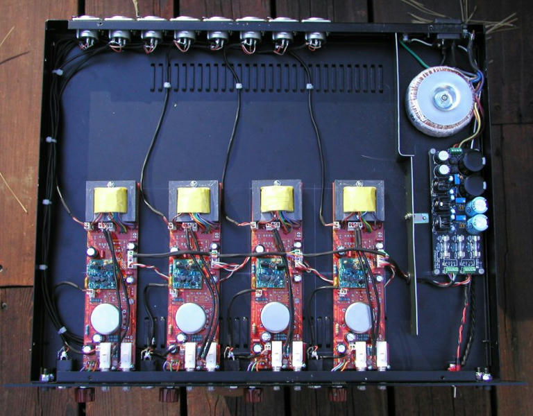
I've got my unit pretty much finished and there is a LOT of gain available! I'm fighting some hum issues due to the proximity of the PS to the 3rd and 4th channel boards, but I'll get that sorted out when I get some more time to do some tweaking. I used the GAR2520 DOAs in my build and they sound pretty damn great.
Cheers,
--
Don
mitsos
Well-known member
- Joined
- May 4, 2007
- Messages
- 2,886
I tried a few zobels a while back and didn't really like them. I felt they kind of put a veil on the sound. BUT, in this thread:
http://www.groupdiy.com/index.php?topic=39800.0
Kevin used 120pF/20K and thought it was better. I have yet to try this one.
in the end it's up to you and your ears what you prefer.
cheers!
http://www.groupdiy.com/index.php?topic=39800.0
Kevin used 120pF/20K and thought it was better. I have yet to try this one.
in the end it's up to you and your ears what you prefer.
cheers!
hey mitsos!
I finished my first api312! sounds great - what an improvement to my rme pres ;D
I just want to optimize my noisefloor, with full gain I measure -73dB RMS in digicheck but I think this can be improved.
do you use shielded cables for the xlr connects and if, what do you do with the shield, let it float (since pin1 is not connected to the pcb)?
also I recognized a big popping sound when de + activiating the phantom, is this normal?
AND MOST OF ALL THANK YOU FOR YOUR EFFORT! this pre sounds just great!
best, martin
mitsos
Well-known member
- Joined
- May 4, 2007
- Messages
- 2,886
Cool!
As far as shielding, I use shielded cable for in/out, and tie the shields to Pin1 of the XLR (and thus to case ground). Consider the cable shield as part of the preamp case. The output may not be as important but I'd definitely do it on the input. I also use a shielded quad cable for connecting the daughterboard, and connect that shield to the ground pin on the preamp PCB.
Phantom "popping" is normal, you always want to mute your monitors when turning on/off.
good to hear they're getting done!
cheers!
mac
Well-known member
Anyway, I'll email the etch files/schematic to you, does your email start with "aw"?
hey Mitsos,
Yeah thats it
awsunnycoast at gmail dot com
I love etching my own boards - real sense of achievement.....
Mac
idylldon
Well-known member
All done. It works like a champ and is as quiet as a mouse pissing on a cotton ball. OK, maybe not that quiet.
Some really bad pics:
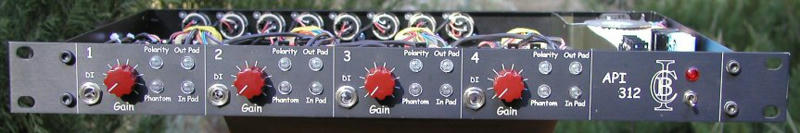
Thanks to everyone who had a hand in this! Now I've got six channels of 312 on tap.
Cheers,
--
Don
Some really bad pics:
Thanks to everyone who had a hand in this! Now I've got six channels of 312 on tap.
Cheers,
--
Don
congrats Don!
looking great! Nice frontpanel too!
Has your channel closest to the psu more hum or noise than the others?
I am thinking about integrating the psu in the case aswell, thats why I ask...
I hope I find some time this week to finish mine. too busy these days with other things.
cheers!
looking great! Nice frontpanel too!
Has your channel closest to the psu more hum or noise than the others?
I am thinking about integrating the psu in the case aswell, thats why I ask...
I hope I find some time this week to finish mine. too busy these days with other things.
cheers!
Yes, really nice!
How did you mount the PCBs, the output transformer bolts through the case as well?
How did you mount the PCBs, the output transformer bolts through the case as well?
idylldon
Well-known member
mrcase said:congrats Don!
Thanks!
looking great! Nice frontpanel too!
I'm lucky since I'm part owner of a laser engraver, so whenever I need to burn a panel there's no wait and no fuss.
Has your channel closest to the psu more hum or noise than the others?
No, but I did put that shield in and also wrapped some mu-metal around the toroid to ensure that it's a quiet as can be. The mu-metal wasn't installed when I took the pic. There's no hum at all, and only some faint white noise at full gain, which is to be expected since there is a LOT of gain. I doubt I will ever need to run these wide open, so I don't think it will ever be a problem.
Originally, I thought I had a lot of hum/noise, but then in yet another "duh" moment I realized that I was running the output of this unit into the input of my other API 312, which means gain-o-matic! I have a patch bay that goes through the wall from my live room to my control room, so I just plugged my new API into it and then forgot to take the other one out of the signal path. Once I figured that out, the new 312 pre turned out to be really quiet.
Cheers,
--
Don
Similar threads
- Replies
- 2
- Views
- 2K
- Replies
- 102
- Views
- 25K
- Replies
- 1
- Views
- 3K