MK47 PCB tube mic kit - build thread

GroupDIY Audio Forum

Help Support GroupDIY Audio Forum:

This site may earn a commission from merchant affiliate links, including eBay, Amazon, and others.
wave said:
Monoklang said:
Dave,

I'm waiting for a couple of missing parts for the Psu. Then I will built it, but then I will tell you how it sounds. So until then I have no clue how it sounds. But do you the answers to my questions above? The thing about soldering the capsule wires above the glass tubes?

Regars

John

John,
Honestly I can't see why it would matter but if it does maybe Max will chime in. Maybe the glass isolators are just there to give stability to the ends of the pins and keep them from touching the board. I can't see what the difference is in soldering on the top or bottom.

Dave

I think that the glass isolators are there because that part of the circuit is the high impedance part.  At the impedances that we are talking normal insulating materials are sometimes not insulation.  I believe that is why Max has chosen to float that part of the circuit in mid air & has told you to make sure that certain valve base pins are not touching the pcb.  So ..... it might make a difference !
 
electrisizer said:
david-p said:
electrisizer said:
is there any clue for this problem?

Yes.  What is the resistance of your meter?

David

its > 7.8 Mohm


This is not high enough for you to measure the polarizing voltage AFTER the large resistor and across the capsule.  For this reason, you get a lower reading than the truth.

David
 
The power supply leaves me with two questions. The two resistor sections: 1k/choke and the 680r/330r. Do attach both of the choke and the 1k or just one. Same goes for the 680r/330r, do I solder them both or just choose which one value to use. And if the latter how do I choose whether to use 330r or 680r.
 
hi funkymonksf,
you only need one of the options in each section your question is referencing.  either use a 1K resistor or the choke.  either use the 680R or the 330R.  the choke will provide less noise and the 680R or 330R really depends on your power transformer output.
with my build i used the choke and ended up using the 680R and was able to adjust the B+ to 105V exactly with the 500R pot (under load).  if you find that your voltage is too low under load you could try the 330R.  hope this helps.
best regards,
grant
 
thanks grant i appreciate the help. Have you finished your build? If so have you posted pictures? I would love to see more completed microphones.

Brice
 
hi brice,
yes, my MK47 is finished and burned in, but no real studio tests yet.  going to finish my MK7 build first and test both in studio.
sorry, no time for pics...my 2 year old and 2 month old are taking all my time right now.  psu built on perfboard and in a little enclosure i got cheap and powder coated at home.  all works great and sounds great though.  mic is in a EQU47 body.

forgot to give a great big thank you to max for the project!  max you are generous and design some great mic projects - THANK YOU sir!

kindest regards,
grant
 
dissonantstring said:
either use a 1K resistor or the choke.  either use the 680R or the 330R.  the choke will provide less noise
Actually, the advantage of the choke is not a noise issue. Being largely inductive, it will reduce the ripple without getting as hot as the resistor.

David
 
max,
i do hope things are better and brighter.  we do enjoy your ideas, projects and participation in this forum - you are appreciated.  please be well.

david-p said:
Actually, the advantage of the choke is not a noise issue. Being largely inductive, it will reduce the ripple without getting as hot as the resistor.

David

david of course you are correct...thank you for that correction. 

 
I am using the antek AS 05T200. It seems to be a good canadate. I do however hate unneeded coils. It always makes me nervous simply tying them off. Especially 180 volts!
 
Isn't there a 6.3V on there that you can use for a jewel lamp?

I went with the LED method but may order a jewel lamp (fender gtr amp style I think) at some point since the transformer has the tap and it would be easy-squeezy.

Cheers,
jb

 
funkymonksf said:
I am using the antek AS 05T200. It seems to be a good canadate. I do however hate unneeded coils. It always makes me nervous simply tying them off. Especially 180 volts!

Brice,
Just cut it and insulate the end with some shrink tube and it will be fine. I believe you will need to put the 680 and 330 resistors in parallel.
You can use the second 6.3VAC tap for a fender style jewel lamp.
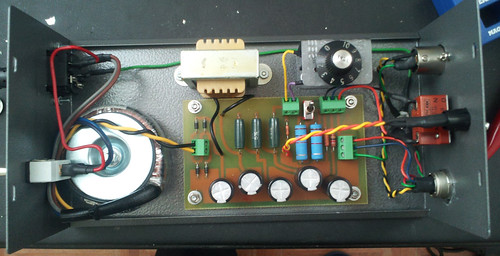
You can use the layout I made for the Poor mans pultec PSU as a guide. The AN-5200 and AN-5240 have the same wire color pinout.
In this case you would use 1- 6.3VAC for the jewel lamp and the other 6.3V (blue+green) would be capped off like the grey 180V line.

Also, I know you like pics so..


Dave
 
dave,
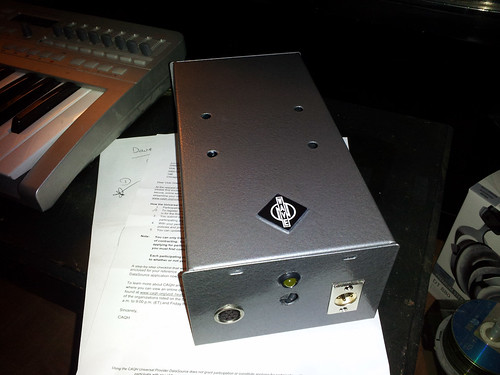
very nice PSU build and homemade pcb no less.  great job!  what enclosure is that pictured?  do you have a pic of the outside?
best regards,
grant
 
Grant,
Thanks for the kind words!
I used this Hammond enclosure

http://www.mouser.com/Search/ProductDetail.aspx?R=1454Pvirtualkey54600000virtualkey546-1454P

Drilled it, epoxied logo on, masked that off, sprayed with primer then hit with about 4 coats of hammered.

This pic my pattern switch wasn't in yet. I ebded up going with 7 pin Amphenol connectors for the mic as opposed to Binder.
I wanted the reliability of having the cable screwed to the jack and the Amphenol made sense financially as well as it was much easier to modify the T-Bone for the male panel end


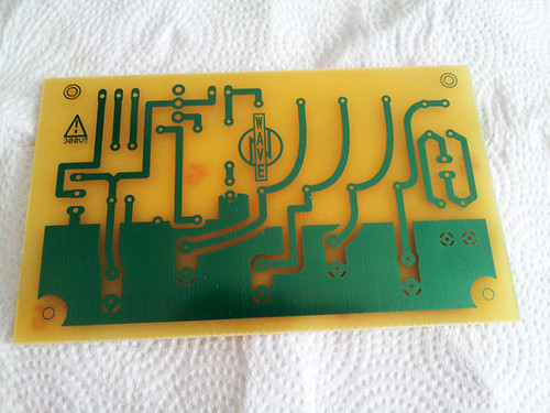
Also here is a photo of my board right out of the etching bath


Gotta give credit to Zayance for his original etch file that I modified slightly for my needs!
Dave
 
Back
Top