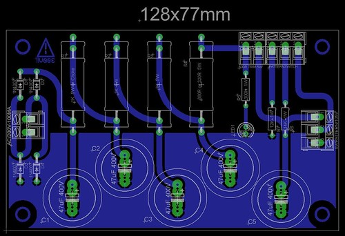
MK47 PCB tube mic kit - build thread

GroupDIY Audio Forum

Help Support GroupDIY Audio Forum:

This site may earn a commission from merchant affiliate links, including eBay, Amazon, and others.
Thanks Max,

Okay, so if 41 VDC is good, what's the high and low of the acceptable range for this spot in the mic?

I pulled the tubes from the working mic, and put them in the mic with ocean noises, and surprise, it works fine now.
I really didn't think it was the tubes because I had thought I tested (and burned in) all of the other tubes from the ubiquitous Phillips 10 pack ebay source. That is a lot of non functioning tubes.

Anyway, despite the ocean noises apparently solved with the tube swap, the high voltage issue follows those (good?) tubes as well. Hmmmmm

I think I'm gonna look for another brand of tubes. 408A I presume are okay as well as 6028?
 
I'm sure there are some reviews in this thread.
There have been some threads on gearslutz as well, just can find this one atm http://www.gearslutz.com/board/high-end/550966-so-im-building-u47-clone-7.html by user JMc (i found this by google-ing ioaudio mk47 )

JW,

i'm not sure where to find good 6028 tubes these days, hopefully other users will chime with their experience.
Some tubes need 48hours+ burn in before they settle.
 
Still wondering what an appropriate range is for the plate voltage. ??

As it stands right now, I've got one mic with 43V at the plate, and another with 47V.

Concerning the tubes, micaddict, those are the same tubes I'm using, though sourced from ebay, 10 piece lot.

I went back to some of the tubes that never seemed to settle, after burning them in for 36 hours or so, and burned them in for 72 additional hours, and that seems to have helped a lot, though, there's still a couple little pops on one mic.

One tube was the culprit in the mic with the high plate voltage (56VDC), and another was the culprit in an additional recent problem: I got all set up to burn in tubes for a long period of time, tested voltages, got a similar reading to what I have now, around 44VDC at the plate, let them burn, came back three days later, to find the B+ up at 300VDC!
The mic seems okay, after having identified another bad tube that was obviously causing the mic to not load down the power supply.

For readers of this thread, who've yet to order tubes, beware that these Phillips tubes can take a LONG time to burn in. A week? Maybe. And count on purchasing a few of them.

I'm thinking about maybe looking at some RCA 408A's, or the Western Electric affiliated ones that are in Canada that I see a lot of on ebay.
 
Hey, I was wondering if someone could clear up a few things regarding my PSU for the MK47.

I am located in Canada and the transformer I am using is the AN-05T200 (http://www.antekinc.com/pdf/AN-05T200.pdf)

The question I have is how should I be wiring the primary wires? Should I only use one set (black - red), wire in parallel (black/black - red/red), or should I wire in series (black/red - black/red)?


Thanks in advance.
-Joel
 
Hi Joel,
I made this for the Poor man's Pultec thread but it applies to this as well.

Dave
 

Attachments

  • AN-05T200_hookup.jpg
    AN-05T200_hookup.jpg
    336.4 KB · Views: 166
wave said:
Hi Joel,
I made this for the Poor man's Pultec thread but it applies to this as well.

Dave

Nice Work Wave ,
Super nice drawing ,
That is great help for everyone,
Dan,
 
Well it's nice to have a drawing for how to wire the mains.
BUT
It's still very important to understand why it is wired like this and how it applys on other power transformer and build etc...
 
Hi folks.  Forgive my cluelessnes but i'm struggling to figure out what power transformer i need for the psu.  i'm in the uk so i need a 240v primary.  I unsure what voltage the secondary needs to be? what V do i want to be hitting the bridge rectifier with in order to be somewhere near 105v at the end? does it need to be single primary and secondary?

i can read the layout of the schematic but i dont know how to wire the IEC to the transformer?  i'm unsure of parallel / series wiring.  Any chance some of you guys could explain in laymans terms where i should start with this. pm probably best.

Cheers

B
 
You want to use a power transformer with a 200VAC secondary. If you use this voltage you don't have to change out components on the PSU.
Some of us use a Triad VPT230 which will output 230VAC on the secondry. Using this transformer necessitates changing a few resistors and the pot.

Here is a Mouser link to the Triad which can be used in both 115 and 230 mains voltage configs

http://www.mouser.com/Search/ProductDetail.aspx?R=VPT230-110virtualkey55310000virtualkey553-VPT230-110

Also this is a great transformer which outputs a 200VAC secondary and can be used for 230V mains and has a couple 6.3 VAC secondaries that you can use to power a nice Fender style jewel lamp

http://www.antekinc.com/details.php?p=603

There is also a power transformer that European users have used in the build. I think it was this one:

http://www.tube-town.net/ttstore/product_info.php/info/p2192_Toroidal-30VA.html

Read the build thread to find out (seems that asking this question means you didn't read the build thread and you should!)  :)

Also, if you figure out which power transformer you will be using then I can help you with the series/parallel wiring question

Dave
 
Thanks for your post Wave,

I have scanned through the thread and picked a few bits up here and there but I didn't really know what I was looking for regarding the transformer.  I did a bit of reading last night.

It looks like the tube-town transformer is best suited for me.  Can you verify: 

From the IEC the earth goes to the chassis, neutral goes straight to the 240v primary?, live goes to a fuse (value?) and then to the on/off switch, then to the primary?  The 200v secondary then goes to the bridge rectifier? 

Looking at Chungers build doc the best place to tap star point ground is off the 2nd cap?   

I am unsure on the pattern select switch wiring.  I have found two diagrams which are different.  One suggests that the 3rd leg of the switch goes to pin 6 of the 7 pin xlr and the other one  suggests that the 3rd leg of the switch goes to the 48v? 


Attachments

  • mk47psu.png
    mk47psu.png
    113 KB · Views: 63
Hey there, just wondering if you could help me out. I bought a mk47 and power supply second hand. The mic worked for about a week but now it pops when tryin to record sometimes. When it started happening if I turned off power supply, plugged out mic, plugged it back in and turned on power supply it seemed to clear the pops for awhile. However now it seems to be happening the minute I turn it on. Any help would be greatly appreciated

 
Burglar,
It's the same difference between the 2 diagrams. If you look you will notice that on the second there is nothing else connected to the pattern "turret" so in theory you could just wire the switch to the 7 pin connector pin 6. Does that make sense?

Your description of how to wire the IEC sounds correct to me. I think I out a 250mA slo-blo fuse in mine. Make sure that if you use an SPDT switch that you wire the live line from the fuse to an outside pin and wire the center pin to your transformer. That will make sure that there is no voltage present on the other unused pin when the power is off

Leitrim-lad,
The first thing I would do with your mic is buy some more vacuum tubes. Those things are notorious for inducing noise and pops. Do you know if the original builder let the tubes burn in for a few days (i.e leave the mic plugged in and powered for 48 hours)?

Dave
 
wave said:
Burglar,
It's the same difference between the 2 diagrams. If you look you will notice that on the second there is nothing else connected to the pattern "turret" so in theory you could just wire the switch to the 7 pin connector pin 6. Does that make sense

....sorry, i dont understand.  when the switch connects the 14k and 12k resistors together it sends 48v down the pattern pin and the mic relay selects omni?  When the 12k / 14k resistor connection is broken by the switch the rise in voltage going to the pattern pin causes the relay to switch to cardioid?

what i cant get my head around is that in neither diagram does the pattern 48v or the 2 turrets next to it go to the 7 pin mic cable, or connect with anything for that matter?.  are they there purely to indicate what the switch is doing when it connects the 12k / 14k resistors?   

Thanks again for your help.

B
 
No. The switch is either taking the voltage from the 14K resistor and sending it to the pattern pin 6 in the 7 pin XLR or its sending it to the 12K resistor and on to 0V. So you have 2 positions:
1. Voltage coming into the switch from the 14K resistor and then going out to pin 6 of the cable
2. Voltage coming into the switch from the 14K resisotr and then going out to the 12K then on to 0V

So when you wire up the switch you would take a wire from the turret the 14K resistor is on to the center pin of the switch then one of the outside pins of the switch would go to the XLR pin 6 and the other outside switch pin would go to the turret that the 12K resistor is strapped to.
It's a bit easier to understand of you look at Zayance's PSU PCB maybe. I found it back on page 19


Zayance if you want me to take this down, please let me know!

Hope this helps,
Dave
 
Hey, thanks for these recent questions - AND ANSWERS - re. specifics on wiring for PSU and polarity switching etc. 
I'm finding it illuminating also.  Just thought I'd say so.  Cheers.
(~:
 
Hey wave, cheers for the reply. I'm not sure if he let the tubes burn in to be honest. It didn't seem to be popping for a few weeks when i got it but its getting extremely bad now. I measured the voltage I was getting from the power supply and it was 117 volts. Is this far to high? Would this be causing the pops?
 
Back
Top