MK47 PCB tube mic kit - build thread

GroupDIY Audio Forum

Help Support GroupDIY Audio Forum:

This site may earn a commission from merchant affiliate links, including eBay, Amazon, and others.
Couple things I don't fully understand relating to this mike:
Has anyone built an mk47 in a gt-2b body as well as an equinox? I wonder what effect the headbaskets might have on the sound?

I'm considering upgrading my mk47 with a Thiersch PVC, and I read somewhere that an m7 has less sensitivity than a k47, so would that ultimately mean a higher noise floor?

Thanks, if anyone cares to drop some knowledge.
 
teacat said:
Couple things I don't fully understand relating to this mike:
Has anyone built an mk47 in a gt-2b body as well as an equinox? I wonder what effect the headbaskets might have on the sound?

I'm considering upgrading my mk47 with a Thiersch PVC, and I read somewhere that an m7 has less sensitivity than a k47, so would that ultimately mean a higher noise floor?

Thanks, if anyone cares to drop some knowledge.

You can go wrong with a thiersch pvc M7. I'm not sure about the sensitivity but it might have something to do with the difference between PVC and MYLAR? The pvc is thicker and less sensitive in the high register.


I've got a question about the polarisation voltage.
My Flea47 is set up for 125v B+ and I've gathered the information that this is fairly common. An old swedish manufacturer, SELA, used M7/K49 in all their microphones and they indreased the voltage from the neumann spec 105v to 120v. Apparently to get more high frequencies, lower noise floor.
Anybody tried this on the MK47? It should be as easy as turning up the voltage to the mike?
/
Emil
 
Hey Emil,

thanks for the kind words.
The voltage devider in the u47 is 2:3 megOhm so the capsule already gets the full 60vdc.
Other mic circuits with fig8 require a 120vdc potential to reach the 60v polarisation per side.
 
ioaudio said:
Hey Emil,

thanks for the kind words.
The voltage devider in the u47 is 2:3 megOhm so the capsule already gets the full 60vdc.
Other mic circuits with fig8 require a 120vdc potential to reach the 60v polarisation per side.

Thanks for the reply!
Do you know if increasing the capsule polarization to over 60dB would cause a brighter sound? It would increase output right? Can the tubes run on a slightly higher ht voltage for a quick test?

I know I read somewhere that it's possible to do a high impedance measurement with a standard DMM? I think it's possible to measure and the calculate given the impedance reference in the DMM but I don't know how. Help...
 
60Vdc is the specified voltage, i wouldn't change anything.
you can measure the voltage between the 2&3meg, before the 100meg.
don't raise B+, the heater would raise too.

 
Hi guys,

my build of mk47 is now completed. However, there is a massive amount of (white) noise.
I already used  a 1,5 K resistor with alu closure, so it might not be the cause for the noise.

Here are the values I have measured:


1-  B+ 105VDC
2-  Heater : left tube pin3: 19.73 VDC; pin4: 37.11 
                  right tube pin3: 1.49VDC; pin4: 19.74VDC
3-  27R  1.493VDC
4-  Backplate 55.6VDC
5-  pin 5: 52.2 VDC


I also tested more than 5 pairs of tubes (all jan type).  :-\

Hoang
 
Most of the Jan 6028 need a long time burning in before their noise goes down.
In some cases the 10nF capacitor got burned from soldering, might be the culprit.


-Max
 
Hi Max,

thanks for the reply. The current tubes were burned in for more than 5 days.  I will try to replace the 10 nF capacitor.

Hoang
 
Hi

I'm hoping someone can give some advice on implementing a permanent voltmeter into a Zayance PCB/Antek Transformer based PSU. Mains voltage drifts around quite a bit where I live.

I've got a 3 wire 0-200V DC meter which requires 7-28V DC to run. I can't find any info on what current it draws.

I am wondering if I should:

A) Power it using one of the 6.3V secondaries on my Antek transformer via an IC bridge rectifier and cap (cap value???) (assuming the 6.3ish volts will be enough)
B) Tap the PSU somewhere near the LED with a series resistor...?

Reading Chunger's "newbie builds..." thread, noise was a problem with his voltmeter...

A filter cap seems to be the solution...I'm not sure what value to use or exactly where to put it, on the meter power supply wire, or 'measure +' wire?...any help appreciated.

Thanks

 
ciscan.81 said:
Hi

I'm hoping someone can give some advice on implementing a permanent voltmeter into a Zayance PCB/Antek Transformer based PSU. Mains voltage drifts around quite a bit where I live.

I've got a 3 wire 0-200V DC meter which requires 7-28V DC to run. I can't find any info on what current it draws.

I am wondering if I should:

A) Power it using one of the 6.3V secondaries on my Antek transformer via an IC bridge rectifier and cap (cap value???) (assuming the 6.3ish volts will be enough)
B) Tap the PSU somewhere near the LED with a series resistor...?

Reading Chunger's "newbie builds..." thread, noise was a problem with his voltmeter...

A filter cap seems to be the solution...I'm not sure what value to use or exactly where to put it, on the meter power supply wire, or 'measure +' wire?...any help appreciated.

Thanks

Matador split the 100K LED resistor into 2 values and we are tapping the meter power supply from there.  It induces noise in that configuration but a filter or smoothing capacitor strapped across the supply seems to have alleviated the noise issue.  The safest thing to do would be to use one of the 6.3V secondaries on a separate regulated supply to power the meter.

We are pursuing the "LED tap" solution to keep the topology simple and be friendly to the readily available 230V toroids that are cheaper, smaller, lighter for shipping, and readily available both in the US and in Europe.

The current prototype using the Antek 200V transformer splits the LED resistor. . . 33K--> voltmeter supply -->67.4K--> LED.  I have a .1uf film capacitor strapped across the voltmeter supply as well.  On my particular meter, with the power supply wide open (unloaded) and in "operate" mode, the B+ goes to 232V and the meter supply tops out at 35.4V.  With a microphone in line and the B+ set to the nominal 105V, the meter supply is 7.6V and the LED is a little dim at 1.8V, but I can live with that.

The main dropping resistors are 750K, 1K, and 500K with a 1K trim pot.

I do not think I can hear noise when I connect and disconnect the meter in this configuration but will test further in the next prototype.  in the studio environment.
 
Thanks Max, I did think that might be a good idea...take the meter out completely when not in use!

I did a bit of reading last night on PSUs with bridge rectifiers and smoothing caps.

I found:

V (r) = I/(f *C)

Where V (r) is the ripple voltage after the smoothing cap, I is the current draw of the load in amps, f is the AC supply freqency doubled (for a full wave rectifier) and C is the capacitor value in farads.

So if I choose to use the 6.3v secondary via an inline IC bridge rectifier and cap to power my meter...

V(r) = (0.08/100*0.001)
      = 0.8V

So assuming 6.3V is transformer secondary rms value: 6.3 *1.4 = 8.8V peak voltage...0.8V ripple is a bit less than 10%.

I guessed at my meter's current draw at around 80ma max (I found a few similar ones stating this online).

So, to someone who knows what they're doing, is my basic theory exercise about right?  :-\

Cap value = 1000uf?

Btw, I chose not to use a resistor in my filter as I didn't want to lose any more voltage as my meter requires 7vdc to run.

Anyway,  I'll pick up some parts this morning and do a test...

Thanks again Max and Chunger.
 
Update on the voltmeter testing for anyone else who is considering it...

I picked up one of these little guys at my local electronics store:


It's a bridge rectifier IC that's good for 1A @ 400V, cost about $1.

I also got some different value 16V caps, a couple of 1000uf and a 2200uf.

I installed the rectifier circuit like this:


Cap soldered across the DC + and - output terminals of the rectifier.

I went with the 2200uf as it seems the prevailing wisdom is that larger values = less ripple. I wasn't sure what the meter would tolerate.

Blue/Green wires are 6.3V AC from my Antek transformer and Red/Black are my (hopefully sufficiently smoothed) DC voltage output.

I temporarily hooked it all up to the meter for testing and it all seems to work ok.


A few observations:

  • The AC voltage from the transformer, before the rectifier was about 6.7V
  • After the rectifier and cap the DC voltage was 7.6V while loaded with meter. (my understanding of this is that the transformer secondary delivers 6.3V AC rms whereas the cap is charged at the peak voltage of the waveform.
  • The voltmeter reads about 0.15V higher than my DMM.
  • I think my meter may be slightly faulty as it switches off and sometimes the reading jumps all over the place when the meter power supply wire is jiggled about. I have a second meter which I'll test out too.
  • Connecting the meter reduces the main PSU DC output by about 0.3V - odd..?
  • My DC output voltage drifts around as much as 0.5V - I am assuming due to mains AC variations.

Hopefully noise won't be a problem in this configuration, once I've got my mic done I'll be able to test. I suppose it is quite possible it may be given my less-than-perfect-DC voltage powering the meter.

If it is an issue I guess it's simple enough to install a filter cap somewhere (as Chunger suggests) or put in a switch to remove the meter completely when not in use (as Max has suggested). With the latter solution,  guess I'll just have to bear in mind the 0.3V increase to the PSU DC output when switching the meter out...

I'm sure this is very simple stuff for those who know what they're doing, but it was a nice little learning exercise for me! 8)
 
...a final update on the voltmeter installation...(with power supplied from 6.3v AC secondary of Antek 05-T200 Transformer)

I decided to design and etch a little PCB (my first) for the voltmeter I installed on my PSU.


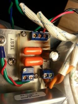
The process was fun and quite satisfying  8). I designed using the popular 'Eagle' software, printed onto some special 'Press n' Peel' paper and then used an iron to transfer the design onto some PC board.  I etched using Sodium Persulphate. I'm sure I broke a few design rules with the layout and tracks, as I got a little impatient, but it seems to work just fine.

For anyone who is interested, the BOM was as follows:

On the 6.3v AC to DC Rectifier side:
1 x Bridge Rectifier DB104 DIL 1A 400V
1 x 16V 2200uf Electrolytic Capacitor (to remove ripple)
1 x 50V 0.1uf Ceramic Capacitor (as a bypass/filter cap)
1 x 50V 0.01uf Ceramic Capacitor (as a bypass/filter cap)

On the 105V supply DC 'measure' side:
1 x 5k (1/2 watt) trimpot (to allow adjustment of the 'measure' voltage the meter sees)
1 x 630V 0.1uf Sprague 'Orange Drop' Capacitor (as a bypass/filter cap)
1 x 400V 0.01uf Sprague 'Orange Drop' Capacitor (as a bypass/filter cap)

In/Out
2 x 2-way terminal blocks (one for 6.3V AC, and the other for earth/105V 'measure')
1 x 3-way terminal blocks (for the 3 meter wires (supply+, earth and 'measure')

I included the 5k trimpot to give me some adjustment on the meter reading. I have tried 3 different meters, and they were all inaccurate by up to 0.5V. I just turned the pot until the meter was reading the same as my DMM.

I put a couple of bypass/filter caps across the 105v section as a 'just-in-case' measure to prevent noise getting to the mic. (Chunger mentioned that he got a little bit of noise when installing a meter, which he fixed with a filter cap.)

Same goes for the smaller value caps on the 6.3v side, I'm sure they're not doing much but "just-in-case"...  ;)

Now to finish my mic and test! :)

Many thanks to Max, Zayance, Chunger and Matador for making this great project available! 8) 8)

If anyone wants a copy of the little PCB PDF file or schematic, send me a PM.
 
Today I finished and powered up my MK47 and it sounds absolutely fantastic! I have it burning in now and so far everything seems to be working great. I built using: BeesNeez M7 Capsule, Western Electric 408A Tubes, GT-2B Body and Chunger's Point-To-Point Power Supply.

This was fun to build and it's a great sounding mic. Thanks ioaudio!  :)


Attachments

  • IMG_1778_Fotor.jpg
    IMG_1778_Fotor.jpg
    478.5 KB · Views: 65
Did one of these last night.  What a simple seeming, yet challenging build.  A third hand would have made all the difference when bridging all of the Hi-Z components.

A couple of questions.

A - I see Equinox is gone so who has an affordable 47 style body?  Most concerned with head-basket shape and appearance but would like something that looks like a 47.  i see Beesneez has a killer looking kit, but $500 is a bit steep IMO.

B - Had a hard time getting solder to flow onto the Russion PIO cap.  In hindsight I should have used some extra flux but I managed to get it all soldered up.  not my prettiest work though.  At any rate, I did heat the crap out of it while I was working with it, and though it didn't pop or leak I always worry when I hold on heat for too long.  How will I know if I compromised the part?  ...and if I did, I assume this will be a more than adequate replacement

http://www.ebay.com/itm/200837990034?_trksid=p2060778.m1438.l2649&ssPageName=STRK%3AMEBIDX%3AIT

right?

I may pop it in anyway just because I like the red.  ;)

C - Any standard pin wiring schemes?  I know as long as PSU and mic match it's golden, but if theres a "common" way I'd like to follow it.

Thanks for another really great project Max.  I may have to build another now, just because the second will be 300% easier now that i know what to expect going in.  In fact, on the next i plan to solder the jumpers to the floating tube socket tabs before inserting them, then just bend them down and connect as prescribed.
 
I've had some random "crackle" sound in my MK47, I changed tubes, still there. So I spoke with a friend that had change the 1,5 ohm 5w resistor to a 1,5 ohm 10w. So I did, but when I were to connect the right lead to the PCB, that little "solder ring" fell off.

Is there any solution to this, can I jump to another solder point? Or have I fucked up…??

Best regards
John
 

Attachments

  • IMG_1049.jpg
    IMG_1049.jpg
    422.1 KB · Views: 40

Latest posts

Back
Top