Materials for pole pieces in ribbon mics

GroupDIY Audio Forum

Help Support GroupDIY Audio Forum:

This site may earn a commission from merchant affiliate links, including eBay, Amazon, and others.

Whackamole

Member
Joined
Dec 15, 2004
Messages
8
Would any of the magnetics gurus care to comment on materials for making pole pieces? Everybody talks about "iron" but we all know there's gotta be more to it than that!

(I posted this elsewhere, but realized that this might make a good topic on its own)
 
[quote author="Whackamole"]Would any of the magnetics gurus care to comment on materials for making pole pieces? Everybody talks about "iron" but we all know there's gotta be more to it than that!
(I posted this elsewhere, but realized that this might make a good topic on its own)[/quote]

You must use pure iron (ARMCO steel).
It is hard to find for me, but in other countries may be.
And is not expensive.
And after you finish shaping, is best to warm it in hydrogen owen.
(I have plans for ARMCO somewhere)

or,
to use PERMENDUR (It is Fe Co alloy, cca 50 percent each), it is
best material for pole pieces of ribbon mics (Olson used this), but
is costly and must be also warmed in hydrogen owen after production.

or
to use neodymium magnets which forms pole pieces.

There are limitation of induction in the gap what you may obtain via methods.
PERMENDUR higher than 2 T (tesla)
ARMCO higher than 1 T
Neodymium itself 0.5-0.8 T

If you want to make much Teslas in the gap, you increases the sensitivity
by linear, and also increases lower frequency modulus transfer corner
(ribbon sees inductance of the mic transformer via Bl gyrator as compliance)
.

By ather words, it is not optimal to increase gap induction higher than 1T
if you use standard permalloy in the mic transformer.

xvlk
 
I really have very limited experience, just a couple of half finished prototypes, but if you are using neodymiums, you can just use the magnets themselves. If you are just trying to increase the size of the magnets, any iron or steel should work (not stainless steel). The baking greatly increases the magnetic permeability (I think that?s the term :?: ), but is probably not necessary, others around here have gotten by without it. I know I read somewhere that cold or hot rolled, works better than the other, but can not re-find the information.
 
Thanks for both the replies. Interesting information there.

What I was thinking of doing was using some big, honking cylindrical Nd magnets (just under an inch in diameter and an inch long), located crossways at the top and bottom of the mic, with the pole pieces to get the flux down to the ribbon. A lot like an RCA-77 style in layout, but without any of the labyrinth stuff, I just want a nice figure 8 pattern. I figure with the Nd magnets, I can get what all Americans crave. . . "More!"

Seriously tho, my real concern is that I won't actually be able to transfer the huge magnetism of the Nd's to the ribbon area of the poles effectively. What's the limiting factor in this application? Is it just saturation? My primary goal is to boost mic output, but there seems to be some other effects as well.

For now, I'm fooling with small, flat Nd magnets and using them directly. Am I wasting my time trying to improve on this by using bigger magnets and pole pieces?
 
> my real concern is that I won't actually be able to transfer the huge magnetism of the Nd's to the ribbon area of the poles effectively. What's the limiting factor in this application? Is it just saturation?

In 1933, it was mostly about how big a magnet you could hang on a stand. I doubt the classic RCAs approached very close to pole saturation. At that level, plain hardware store iron is fine. Remember you have a BIG air-gap in the path, any kind of iron is almost 1,000 times better than air.

As smilinfu says, with the super-hot new magnets, pole pieces are almost a waste of time. Hard drives, where the magnetic system is engineered to DEATH, no longer use pole-iron. It is no longer necessary to funnel-down the flux from a big hunk of Alnico or ferrite to a small pole; the magnet is a fine pole by itself.

> My primary goal is to boost mic output, but there seems to be some other effects as well.

There is such a thing as "too much" flux. Too much magnet on a cone woofer raises midrange and relatively reduces output around resonance, giving "soft bass". The same can happen in a ribbon: more bass and midrange, but the top octave gets a heavy mechanical resistance loading, especially with non-infinite electrical loading. To figure if that is a problem, you should draw impedance graphs for every part of the system, as Olsen does. But that is a lot of work, I'm not sure anybody really does that, or even that Olsen really relied on those charts.

Getting high output from a ribbon is fighting the ribbon's virtue. No passive device can be both high efficiency and broad-band. The ribbon can be broadband only when its efficiency is lower than a dynamic mike. The dynamic has a much better ratio of diaphragm area to conductor mass (and a more efficient magnetic gap) so tends to give higher output if you do not demand great bandwidth.
 
[quote author="PRR"] No passive device can be both high efficiency and broad-band.[/quote]

Hi PRR,

That caught my attention. I can see this 'intuitively', but can you point me in the direction of some theory or maths that leads to this conclusion?

Cheers!
Stewart
 
[quote author="zebra50"][quote author="PRR"] No passive device can be both high efficiency and broad-band.[/quote]
[/quote]
Resistor ? Is passive, broadband, NOISY... .
xvlk
 
[quote author="Whackamole"]
What I was thinking of doing was using some big, honking cylindrical Nd magnets (just under an inch in diameter and an inch long), located crossways at the top and bottom of the mic, with the pole pieces to get the flux down to the ribbon. A lot like an RCA-77 style in layout, but without any of the labyrinth stuff, I just want a nice figure 8 pattern. I figure with the Nd magnets, I can get what all Americans crave. . . "More!"

Seriously tho, my real concern is that I won't actually be able to transfer the huge magnetism of the Nd's to the ribbon area of the poles effectively.
[/quote]

Yes, you are right. Because of all the losses in iron you will transfer only a few %% of magnetic energy in this configuration. In fact, you won't be able see too much difference in sensitivity between using ALNICO or ND in this configuration. Permendure will give you better efficiency, but material alone can cost as much as good ND magnets.
The only way is to use ND as a pole pieces. This way you don't need even a magnetic return path.

My primary goal is to boost mic output, but there seems to be some other effects as well.

Yeah, that's the goal of all ribbon mic designers..., but the problem is you cannot boost an output of the ribbon mic without sucrifising other parameters of the system.
 
Well, I put together a ribbon mic without any pole pieces just to see how well it would work. First crack out of the box wasn't too bad at all! That's something, considering I used a crappy ribbon I had whipped out as a practice piece. It's not totally parallel, but was not too awful. It's also made from capacitor aluminum (I had some brand new stuff) that's about 4-5 microns thick. Too thick, I know, but the sound is better than I had hoped. I'll get a proper aluminum leaf ribbon in there and see what happens.

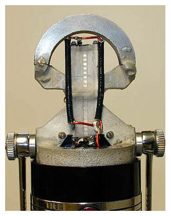
This is just a test rig, not ever intended to go into a housing or anything. If I can get it sounding good, I'll build another one to put in a nice brass housing. What you see here is:

1/4 inch black plexiglass body with series of 1/2 inch holes.

A slot in the center to accept 2 50mm X 2.5 X 5mm magnets (I used a third magnet with some notecard wrapped around it to give me the spacing I wanted) The magnets are just epoxied in place. The magnets are flush with the front of the plexiglass, as is the ribbon.

The contacts are made from copper clad PC board (one sided) and the wires are soldered to the "back" in the picture. You can also see some 1/4" holes to allow for clearance of the soldered areas.

The trafo is a Lundahl ribbon mic type.

This was all made with simple tools, no milling machine, just a bandsaw, drillpress, and some files.

NOTE TO RIBBON MAKERS: Try one of those "wheel" type cutters used for cutting fabric to cut your ribbons. They look like a small, razor sharp pizza cutter. Works great! I'm still coming up with a good jig to make the ribbons easily, but it will be used with this type of cutter for sure. Pictures of that jig when I have them.

In the meantime, I welcome comments, positive or negative.

TestRig2.jpg
 
[quote author="Whackamole"]
TestRig1.jpg
[/quote]
You wires to ribbon are too thin,
and you not uses any hum - bucking.
Is (random) noise from your mic adequate ?
What about self - noise, did you some measurements ?.
Is noise from your micropheone adequate to your
nearly perfect design. Have a fun, you are going right way.


xvlk
 
I did wonder if the wire-wrap wire was a bit thin! :shock: I hoped that the fact it was silver coated might reduce the resistance a bit. What gauge wire should I really be using? Solid or stranded?

All I did for humbuck as you can see is twist the wires together a bit. It wasn't bad, considering it had no EM shield at all. Some noise, but that may be from the amp more than anything else. I'm using my old Ampex reel-to-reel and just feeding the mic into that and back out the lineout to my computer for doing digital recording. This has worked decently for my Electrovoice 664 dynamic mic. There is some hiss going on, but it's not overwhelming. No real self-noise measurements yet, as I don't have a lot of instrumentation, and audio was never my strong suit anyhow. Any simple setups I can rig?

I'll try to come up with a good way of finding the resonant freq once I get a good ribbon and some wind and EM shielding over it. The trafo is set up for 37:1, is that probably going to be somewhere near what I want or am I going to have to make more measurements to really get that right? I could rig the trafo with a set of switches if I had to.

Thanks for the input. I've "improved" the picture in the previous post a bit, so you can see it better. Have a look.
 
Dear Whackamole,

Such a great start! I am sure, with a thinner and lighter ribbon it will sound great as it is!

Of course, as always with anything, some refinements can be made. Here is some food for thoughts.
First, you need to deside what kind of compromises you are willing to make. Do you want to optimise the system for the best HF response, or for maximum output, while still keeping HF adequate for "Hi-Fi" performance?
It seems that the magnets are mounted with large surfaces fronting each other. Together with 1/4 thickness of the plate, it creates deep cavity, which potentially could lead to some parasitic resonances and reflections. For your final version I'd use stands glued to rear of the magnets. Look at my avatar--it will give you the idea as for what I mean.
The PCB clamps are great for prototype, but are prone for oxidation and as a result, you get noise increase, or even contact loss, in a long run. I'd whether silver or gold plate them, or use brass plates (BTW, it would be a good idea to plate it, as well).
With aluminum leaf, you've mentioned, you will run into another problem. Since it is extremely thin, its resistance will be too high, and with the Lundahl transformer you have wired as 1:37, mic self noise will be too high. Cures for the problem: 1) wire the trafo as 1:9, and then use another 1:5--here there are lotsa other problems, such as transformer loading, etc. 2) Custom made trafo, or DIY it, 3) use shorter or wider (or both) ribbon. Once again, it involves some other problems: shorter ribbons are prone to resonance modes and need acoustical damping--you don't want to get into this stuff. Wider ribbon reduces magnetic flux, but you could do it. Considering the polarized faces of your magnets are 5mm wide, in present form a lot of energy dissipates due to this fact, and the system is out of saturation. Pole pieces with let's say 1/16" tips would greatly concentrate energy of your magnets, so you could easily make the distance between your magnets wider. Magnetometer would be very helpful here, so you could find an optimum width, where the flux is about 0.5T.
And the easiest solution--4) use thicker ribbon. From my experience, something like 1.8-2um would work great with this transformer.

The wires from the ribbon can be made much thicker and shorter. Old ribbons use about 1mm (whatever gage it is) solid copper. For humbucking use two wires from top of the ribbon, where each wire could go whether from front and back of ribbon, or on the sides of magnets.

BTW, the roller you are talking about might work fine with thicker materials, but with very fine stuff, most likely will tear it. Usually, I use a razor blade, and cut the foil, placed between two pieces of transparent paper. More sofisticated cutters look like a gilotine (spelling???) heavy blade.
 
Marik,

Thanks for the tips, much appreciated. I'm still blown away that it works as well as it does for being so utterly non-optimized.

The magnet orientation was an artifact of the magnets I could get. For a few dollars more I could special order the same size with the orientation through the width rather than the thickness. Now that I know I have some chance of it working, I may do just that. At the very least, it's worth looking again to see if anybody has them stock. What about a cylindrical magnet with the orientation through the width? That would get a concentrated pinch point between them, as long as you got them installed correctly.

I agree that having the little "magnet tunnel" in the back will cause some odd reflections. I can hear it when I speak at the back of the mic, in fact. Just a little ringy. Getting a higher flux would be nice, as the output seems pretty low and I think I'm just using too much amplification and getting lots of hiss from that. Sounds like a 78 record, which isn't bad for the kind of stuff I tend to record.

2 micron ribbon would be nice, but there seems to be no cheap way to get it. Did I mention I am cheap? :green: But that was part of the plan, to try different thicknesses and various sources of ribbon material. I'll be peeling aluminum off of Gyros wrappers and Wrigleys chewing gum before this is all over.

The PCB contacts are just a simple workaround, I'll be changing stuff often for a while at least, so they can be cleaned whenever I do that. I'll put a little R5 Power Booster on them too, and that may help. Gold plate eventually for a finished model for sure.

I think I know what your saying about the humbucking arrangement, but a picture would really be a help. A posting or URL or anything you could direct me to? 1mm wire is about 18 ga, just FYI.

As for the roller cutter, the plan is to always have the ribbon between two pieces of paper while cutting it. My initial experiments have been good, and I actually think there is less chance of a tear because of the rolling action rather than a sliding/cutting action. I'll let you know how it goes when I get the jig made. If I had a decent guillotine paper cutter, I'd use that.

I stuck the trafo way down at the bottom (it's hotmelt glued to the plexi, BTW) because I wanted as much room as possible for my (suddenly) bratwurst-sized fingers to get the ribbon in place. Guess I could mount it off to the side or on the back and a lot closer to the works. It's like making waffles, you know you are going to throw the first one away!

I really enjoying this so far, but I'm going to keep my day job for just a while longer. All this help is super, I'm impressed that nobody has played "Kick the dilettante" with me yet. Is it worth me posting a sound file sometime? My first trials sound OK through the headphones, but impossibly bassy through the speakers. Could be that my speaker system is krep, not sure. Wouldn't surprize me one bit!
 
[quote author="Whackamole"]
2 micron ribbon would be nice, but there seems to be no cheap way to get it. Did I mention I am cheap? :green: [/quote]

Tell me that... We all are :grin:
But seriously, if you want to get really good results, to get the right foil is cheaper.
As for the "right " polarization of these magnets... I spent many hours on internet searching for those and diametrically polarized rods, with no luck. If you meet them somewhere let me know.

My first trials sound OK through the headphones, but impossibly bassy through the speakers. Could be that my speaker system is krep, not sure. Wouldn't surprize me one bit!

Ribbons have a huge proximity effect. Try to record at least a couple feet away.

I think I know what your saying about the humbucking arrangement, but a picture would really be a help. A posting or URL or anything you could direct me to? 1mm wire is about 18 ga, just FYI.

Look at RCA77C:

77c1.jpg
 
I just finished reribboning my Shure 315. I used the rotary cutter along with a cutting ruler from a fabric store, and the craft store aluminum leaf, which is supposed to be sub-micron? Only took me three tries. It works great, much wider frequency response than my Shure 330 (same magnets, same transformer, but cardioid) which could probably also stand a new ribbon. Output is about the same, not enough difference for me to bother measuring.

I've never used a high-end ribbon, so I only have these two to compare.
 
> 1mm wire is about 18 ga, just FYI.

That's about what I have seen in ribbon mikes.

There is not enough silver on wire-wrap to reduce the resistance. It mostly protects the copper.

And they mount the transfo right under the ribbon to keep the wires as short as possible.

The idea is: ribbon resistance is "good" because it is also signal. But wire resistance is just bad. You want most of the resistance around the primary to be in the ribbon, not in wiring. Same as, when you use a power tool, you use a fat extension cord so you lose the least power in "dead-loss" wiring, the most power in the tool. But a ribbon mike is orders of magnitudes lower resistance than a Skil-Saw, so you will be using very short lengths of power-gauge wire.

Can you compute (or measure) the resistance of your ribbon? As a first approximation, you want the transformer to make the ribbon look like 100-300 ohms at the secondary. Your 1:37 tranny suits a 0.15Ω ribbon.

The twist is good but you have a loop: the ribbon and the lead wires. This captures hum fields. It may be OK in your shop, and will probably hum like a carpenter when stuck near a guitar amp. Details to try later: use two wires from the top down to the bottom. One on each side. That makes two loops, but in anti-phase. It gives some reduction in hum.

Sensitivity: ultimately, a ribbon can be about as "hot" as a dynamic. They are generally less-hot, because dynamics are good and cheap; if we want something better, we accept some loss of sensitivity in exchange for smooth bandwidth. But (when everything is tuned and matched) you should be able to use it at nearly the same gain setting as a dynamic. If so, your noise level will ge good.
 
>Can you compute (or measure) the resistance of your ribbon? As a first approximation, you want the transformer to make the ribbon look like 100-300 ohms at the secondary.

The corrugated 2"x1/4" ribbon from a leaf (probably ~0.6um) has 0.85 Ohm, measured on my GenRad 1650A bridge. With LL2911 transformer wired as 1:37, it has unacceptable noise, even when unloaded. 1:18 is better, and with 1:9 it becomes more or less usable, but the output is very low without another transformer.
 
PRR,

I see what you are saying about the resistance. Makes total sense.

Just as a mental excercise, would there be an advantage to having a composite ribbon of some sort? Here's what I'm getting at. You want the flat ribbon shape for its physical motion properties, but you want to be able to have the conductive property as controllable as possible. I haven't even attempted the math here, so I may be off by a long shot, but imagine, say, a 2 mil mylar ribbon, corrugated as usual, but with very fine copper or silver wires attached centrally along its length (oh hell, I seem to remember seeing something like this someplace. I'm plunging on regardless! Reinvent the wheel? Why not?) The multiple wires increase signal, up to the point where the mass penalty will negate any advantages, will they not? You can have some control of the resistance of the wire by your selection of material and diameter, and that would be independent of the "ribbon" itself, which just acts as a substrate and accustic pickup.

Actually manufacturing such a composite ribbon might be a real PITA, but having the ability to tune the characteristics more closely could have some advantages. Again, I'm just talking off the top of my head with the aim of keeping the conversation going in the hopes that some new notion might drop out of it.

Then again, maybe we should just cut out the middleman and make a gadget that gives your brain the sensation of listening to really great music without there being any music at all. From what I'm seeing, that might be as technically easy as making a really good ribbon mic :wink:
 
Whackamole,

Yes, Fostex made a printed ribbon. For some reason (may be just marketing), it did not get much success. Unfortunately, I never had a chance to listen to it.
I don't think what you are proposing would work as it is impossible to corrugate a mylar. It just won't "remember" the shape. It is possible in ribbon speakers, Apogee for example, where a copper (?) foil, imprinted on Mylar base, is much thicker and mainly responsible for holding the shape of corrugation.

Any other opinions?
 
Would you really need to use mylar? How about a thin parchment or maybe rice paper? The only thing I can think of is that they may still be too massive, and they would be heavily affected by humidity.

So what other materials could be used?

Maybe something like Saran Wrap? It wouldn't hold its corrugation, but as long as the wire did...
 

Latest posts

Back
Top