1940's tube compressor side chain bypass(?) example

GroupDIY Audio Forum

Help Support GroupDIY Audio Forum:

This site may earn a commission from merchant affiliate links, including eBay, Amazon, and others.

emrr

Well-known member
Joined
Apr 12, 2006
Messages
8,536
Location
NC, USA
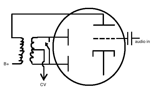
Here's a drawing of a typical 1940's era compressor side chain, with a switch I've not seen implemented.  We have a triode/dual diode tube that amplifies the audio, and gives rectification through the secondary of the plate transformer at a 1:1 ratio, with the control voltage taken from the center tap.  

The part I've not seen is the switch to short the rectifier plates together.   In practice it's sort of bypass, but I'm still getting some control voltage output at a much lower level.   It doesn't thump audibly at all, and that may be the sole reason for this approach.  

Would you call this bypass? With a change to half wave inductively limited rectification of leakage and secondary imbalance components?

I've not shown it, but the switch is a DPDT, and the other section turns a pilot light on and off, off when the rectifier plates are tied together.  I'm looking at four of this particular limiter at the same time, and they all have this circuit.  
5121010746_8f71551fbc_o.jpg
 
How much does the threshold change with switch in?  Thump when open to no thump when closed?
 
It's actually an AGC, so it's difficult to tell how much change occurs.  This thing is designed to have a pretty good amount of reduction at all times.  Maybe 3-6 dB increase in output.  Meter suggests drop from 20 dB GR to 10dB.  There is no thumping at any time, and no switch noise either.    There is a large increase in distortion components, which seems to be related to the unit hitting the output ceiling, as would be expected with hitting bypass on a similar circuit.  A reduction in input removes any distortion. 
 
emrr said:
Would you call this bypass?
I would...
With a change to half wave inductively limited rectification of leakage and secondary imbalance components?
There should not be much to rectify, because the triode's output is shorted, so its load is only the Rdc of the xfmr. It's rather crude, but acceptable in view of the restricted quality of the rest of the chain.
 
eskimo said:
Got any schems of the full circuit?
Yes, but none that I'm handing out on this one, sorry. Other than the switch, the side chain resembles the RCA 86 limiter, and many others of the era like the Collins 26C, with single ended audio taken from a point within the circuit and amplified in parallel and then rectified with a 6R7.  The amp section is the typical PP vari-mu.  By the 1950's it became standard to do away with the phase splitter transformer wrapped around a 6R7 triode/dual diode, and replace it with PP audio taken from the output of the amp, and fed into a dual diode.  
 
abbey road d enfer said:
There should not be much to rectify, because the triode's output is shorted, so its load is only the Rdc of the xfmr. It's rather crude, but acceptable in view of the restricted quality of the rest of the chain.

I can only assume there's enough imperfection in the placement of the secondary center tap, and leakage components, to give some small CV output.  Maybe that's not even possible, and there's another mechanism at play. 
 
Back
Top