Please help verify GroupDIY51X standard dimensions

GroupDIY Audio Forum

Help Support GroupDIY Audio Forum:

This site may earn a commission from merchant affiliate links, including eBay, Amazon, and others.

chunger

Well-known member
Joined
Apr 21, 2008
Messages
1,034
Location
Northern California
Hello,

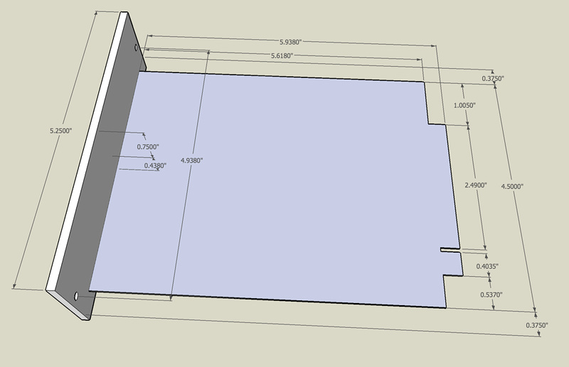
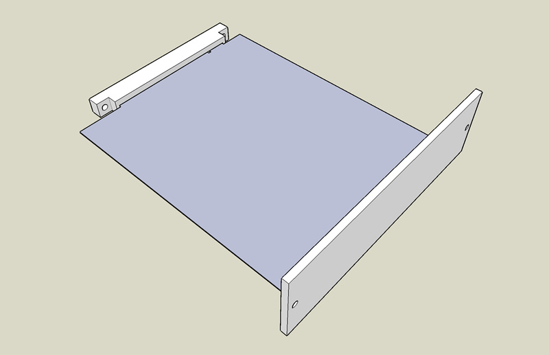
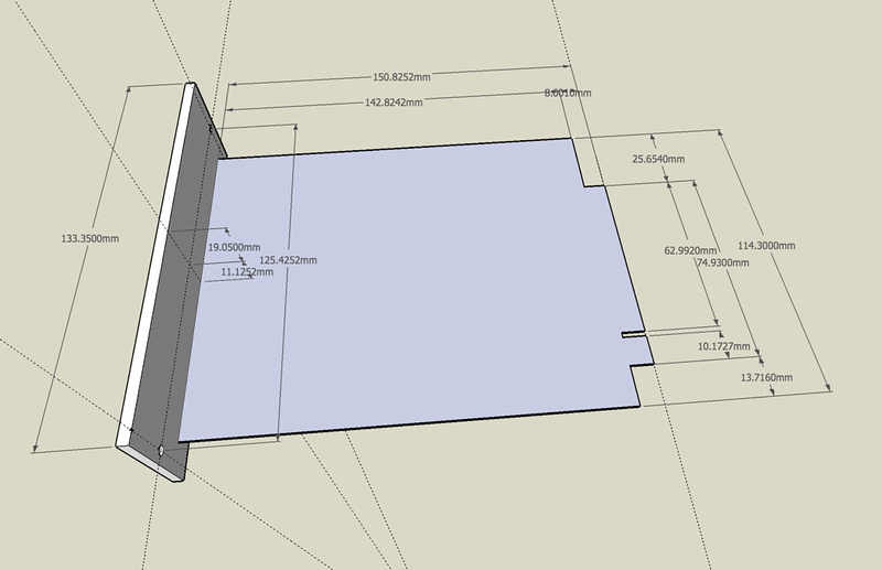
I'm working on getting some small (1 and 2 slot) 51X standard cases fabricated, and wanted to make sure that my underlying assumptions about the card/slot dimensions are correct.  Please excuse the PCB that has no thickness at this point.  I'm just trying to make a template to start from.

I obtained a lot of my dimensions from a file posted in the gdiy gmail account and am guessing at a few others based on measurements from one of Jeff Steiger's vp312 and vp26 boards.

I want to make sure I'm starting from the most accurate measurements possible before proceeding.

Oh, btw. . . yes, I'm biting off more than I can chew, but nobody has a product or kit that fits my application, so nothing ventured, nothing gained.

p921599077.jpg


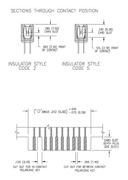
I assumed the original API 500 standard has the card slot centered on the card and the 51X goes from 15 to 18 positions adding those on the bottom side of the card.  Moving forward, next I should precisely locate my PCB edge connector and I'll have all my critical mount points set and can determine case dimensions and PCB location relative to those set parameters.
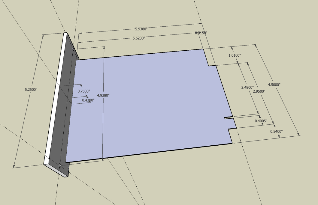
 
hey,
sure someone has inches for you but i think your about right the api edge is centred 25mm in from either side.
there are discussions over the gap to be used for the additional 51x pins to enable lunchbox use for the units designed for that case, but they extend out at the bottom yes :)
 
I guess for my uses, the gap doesn't matter because I'm just making cases.  I'm guessing the 18 pin EDAC connector we're using is 305-036-520-202

Looks like the slot depth is .295" (7.50mm). . . maybe set my model to .290" and leave .005" room for slop?  I'm guessing I should leave a little wiggle room so the cards don't bottom out?

p866426053.jpg


Sorry Metric users. . . here's the model in metric. . . for those who prefer a more "reasonable" unit.

p839474861-4.jpg


hey, cool model. I was thinking about something for 2 modules, but I'll just be making PCBs, metalwork is a little over my head now.
Anyway, good luck!
 
From your drawing, the 0.4380" (11.1252mm) is the distance between frontpanel center and pcb bottom/traceside, not pcb top/partsmounting side. You'd have to subtract pcb thickness from this dimension.

(Just one lick over the edge and the last digit is spot on  ;D)
 
Harpo said:
From your drawing, the 0.4380" (11.1252mm) is the distance between frontpanel center and pcb bottom/traceside, not pcb top/partsmounting side. You'd have to subtract pcb thickness from this dimension.

(Just one lick over the edge and the last digit is spot on  ;D)
Actually, the drawings I have seen show the .4375" dimension from the faceplate center to the center of the PCB, not top or bottom.

FWIW, I think everybody cheats a little bit with stock standoffs and so on. I believe we had this discussion on a 500 series metal thread with Mikefatom.

Cheers, Jeff
 
Hi Jeff,

Thanks for the link.  This cleared things up tremendously.  There were a couple of figures I was using based on physical measurements.  My total slop was .002" so I think what I had would have worked.  I think my methods of scooting that slop around were good because when I adjusted my card edge dimensions to the specs in thread, my edge connector lined dead perfect  ;D  This is reassuring because at least I was able to place that EDAC connector in the right spot.

p390893387-4.jpg


Humans win! 

p493630706-4.jpg


As for what I'm trying to do, it's pretty simple actually and way over my head at the same time.  I want to make 1-3 51X modules portable so I can use it on gig as a bass amplifier.  The VP312DI was just too perfect for the role.  The GDIY51X rack. . . .way too big.  I have located someone who can do my PCB design and source them.  I think I have found someone who can do my sheetmetal fab (at least for prototype).  The plan:

1.  Get a single or double slot case up and running.
2.  I can jam a JLM powerstation into the same size box w/ a 30VA toroid.  This should be able to power 2 cards (preamp, EQ).
3.  A friend is west coast distributor for a speaker company and is making a bass cabinet kit (including build-in amplifier).

This will get me up and running in time for NAMM. . . hopefully my spec bass guitar samples will be produced in time as well.

4.  A friend has indicated he can design and produce a switching power supply for +-24V, +- 16V, 48V. . . hopefully this will give a more usable power rating than the powerstation with small transformer (can use more modules).
5.  Integrate DC power supply with Hypex 700 power amp and have a modular, portable, flexible system suitable for a variety of uses including the original (bass guitar amp).

Items I need to figure out:

1.  How to nest the cases together for ease of transport and use (some random ideas):
    a) simple screw connection with plates
    b) slick magnetic "screw-less" connection
    c) some sort of sleeve that the modules can slide into
    d) just use velcro and gaffers tape  ;D

2.  How to handle module to module connections:
    a) use XLR connectors at back (3pin in, 3pin out, 7 pin in, 7 pin out)
    b) use XLR for audio and some sort of spring loaded blind contact setup for power (Mill-max has some new spring-loaded ones).
    c) find a blind docking connector that can handle everything.

3.  Buffered additional balanced output.  Maybe integrate into the backplane PCB.  I can see the need for this when using the module live and you need to feed your amplifier as well as provide a feed to the house P/A.  Buffered so main signal is not "sullied" by whatever's on the other side of that secondary output.

That about sums it up.  I'm not exactly the best candidate to take on a project like this for lack of electronics knowledge and precision production sheetmetal fabrication, but hey. . . I'll give it a go and see where it ends up.  More exposure for the 51x platform is good. It'll fuel development of more modules.
 
jsteiger said:
Actually, the drawings I have seen show the .4375" dimension from the faceplate center to the center of the PCB, not top or bottom.
Zooming in the drawing it seems you are right and I stand corrected. The other published 'Mechanical for Speck ASC-V' drawing show the same .438" center/center dimension.
 
PCB hole spacing is slighting different between EDAC 305-036-520-202 and the Oupiin 8706-36G00D that I believe is used in the GDIY kits.  The center to center spacing between the 2 rows of pins is 3.96mm on the Oupiin and 3.56mm on the EDAC.  Guess I'm just trying to figure out which one to use if making a PCB. . . or I guess I can try to make it fit both.
 
Hi 'Chung,

The EDAC's that Volker designed the original 51x backplane around were only single row on the back. I think you will find both available from EDAC. When we were putting all the parts together for the 51x kits, the Oupiin connectors just made much more sense to us. The quality is just as good and the price is way better. I should always have the Oupiin's in stock.

Food for thought.

Best, Jeff
 
Excellent. . . I noticed the GDIY board had the center hole option.  I will design for the Oupiin then.  I was mainly concerned because I didn't find a source for them readily, but if you're planning to perpetually stock them, I should be fine.  I'll probably just do the center hole option just like the GDIY rack to accommodate the single row EDAC also.

Newbs. . . with their newb questions  ;D
 
Hello
only for a confirmation about dimensions showed by the images

are the dimensions verified or not ?

peace
r2d2
 
Back
Top