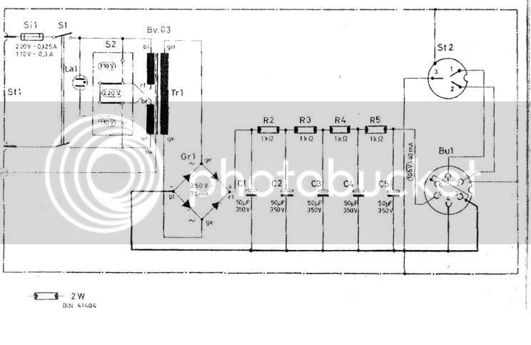
So, with 160V of drop across the 4 1k's...
Add that to the 105V that is left-over/indicated/specified...
Gives us 265V..
The mic is a divider = 2625 ohms (in order to provide 105 at the node).
Start plugging in some number here (and/or elsewhere):
http://www.bowdenshobbycircuits.info/r2.htm
Looks like the 4x 1k's dissipate a total of about 6.4W. P=IE, P=.04A*160V, 6.4W=.04A*160V
I see the PSU schematic specifies 2W. I guess watts add in series because if they didn't, it wouldn't work and they wouldn't have sold many mics.
Now, with 265V at the bridge what does the BV03 need to provide, and what about those 50uf caps?
I see an indication of 250V/75mA at the bridge. Looks like additional info that might be helpful.
Best,
jonathan


 If I knew what it meant or what it was referring to?